Ok then, time to move on to disconnecting everything in the engine bay and all the other pipe work (fuel and brakes). There are also a few various electrical connections as well.
In more detail:
- All the engine bay wiring loom needs to be disconnected.
- The brake lines at the bulkhead block on the drivers side inner wing in the engine bay need to be disconnected.
- The fuel connections to the fuel rail on the engine and the pipe out of the tank at the rear need to come off.
- The heater hoses from the water rail to the heater matrix need to be disconnected.
- The handbrake cable needs to be slackened off.
- The PAS system needs to be drained and the hoses removed at the steering rack
Lets start with the wiring.
In my opinion it looks quite daunting, but actually there aren’t really that many connections throughout the engine, helped of course by the fact that most TVR’s don’t have much in the way of electronic help. By that I mean there is no ABS, no electronic stability programs of any kind, no brake pad sensors, no tyre pressure sensors etc. Less of all of that kind of stuff means less wiring.
Its also worth working out before roughly where the route goes. The main loom emerges from the bulkhead low down on the near side. It then splits as follows.
Near side contains:
- Near side connections to injectors
- Connections onto intake manifold/fuel rail
- Connections onto distributor and coil
- Throttle potentiometer
- Connection to MAF
- Earth connection to engine block
- Wiring for near side exhaust manifold lambda probe
The main body of this run sits between the rocker cover and the intake manifold before moving across the front of the engine to the coil.
Off side contains everything else… Ok ok, that was too easy even whilst being obvious. So…
Off side contains:
- Off side connections to injectors
- All wiring for the alternator
- Stepper motor connection
- Main cable down to the starter motor
- Earth connection to engine block
- Connections too and from the 100 amp fuse
- Connection to front loom in the nose
- Wiring for off side exhaust manifold lambda probe
The main body of this run again sits between the rocker cover and the intake manifold. It then bends around the alternator/belt tensioner bracket before heading straight down and then to the lower side of the engine block.
My apologies, there could well be other random connections other than mentioned above, but those are the main ones that spring to mind at the moment.
I began by removing the distributor cap. On my car all the leads are nicely labeled. If yours aren’t then make sure you note which lead goes to which spark plug. Removing the leads from the plugs, or plug extenders actually, is straight forward. Just pull them off ! (Note, the spark plugs have extenders on them which appear to help keep the leads away from the manifolds and thus any heat damage).
 Numbered lead tidy indicating where they go
To remove the dizzy cap there are 2 clips that clamp it on. Undo the clamps and lift off.
 Clamp shown at bottom of picture in the middle. There is a second on the other side as well
Next up I removed the breather hoses than span the front of the engine from one rocker cover over to the other, and on to the coil and the alternator. The breather hoses just pull off on the near side. There is one connection onto the bottom of the plenum and another into the trumpet base. The last connection is held on with a jubilee clip onto the flame trap on the off side rocker cover.
The wiring for the coil is also cable tied to the hose. Snip off the ties, remove the connections from the coil (making note of which spade connector goes where) and move out of the way.
 Connection onto trumpet plate on near side.
 Connection onto plenum on right of picture
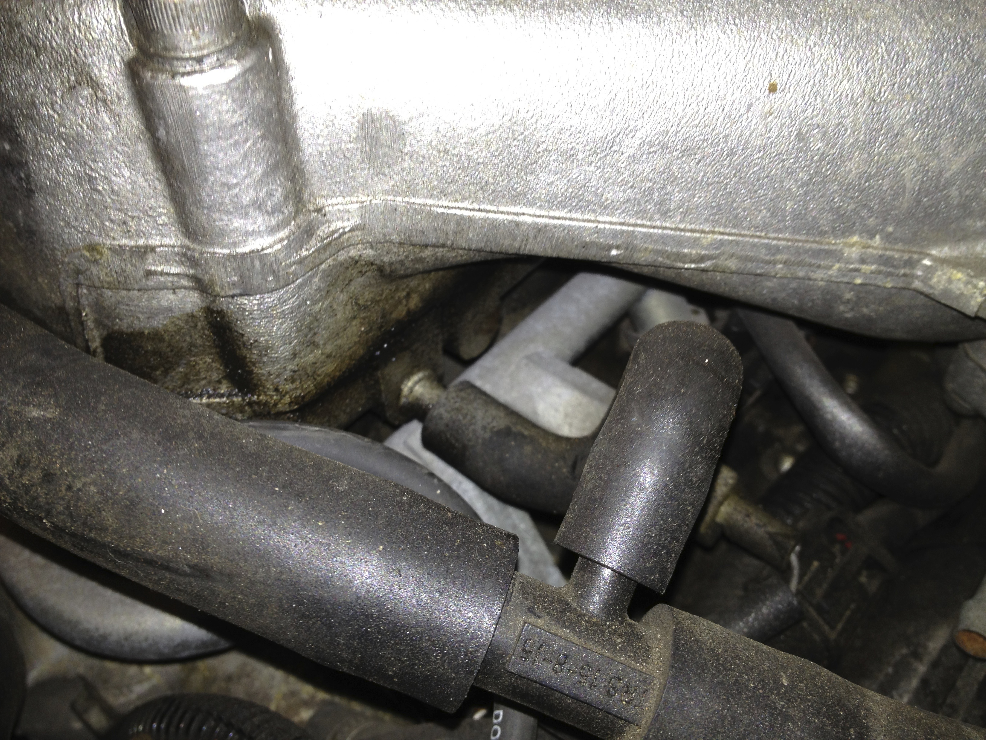
 Connection onto flame trap. The jubilee clip is in the lower centre of the picture. Wiring attached to the hose can also be clearly seen
 Hose coming off the flame trap (Coil has already been removed here)
To remove the coil disconnect the spade connectors, the large electrical connection towards the middle of the car for the ignition module and the main bracket. The ignition module is attached to its own bracket/mount which is in turn bolted to the main coil bracket. The main bracket passes through the forward most off side plenum bolt.
 Coil bracket attachment to plenum
 Ignition module connection towards middle of engine. Spade connectors on coil and lead to dizzy on the left
 Close up of opposite side of coil and its connections
The alternator is attached to a large bracket that also has the belt tensioner on it as well. There are 2 bolts to undo on the bottom half of the alternator. Once undone the electrical connections on the rear, underneath a plastic cover that just prises off, can also be removed (note where they go). The below picture also shows the belt tensioner as the very left most pulley. Place a socket (15mm) on the rusted nut (in my case at least) on the end of a long breaker bar. If you position this so the bar is pointing straight up at the sky just push the bar clockwise as you look at the engine and the tensioner will move on its spring. As it does so the main poly belt will slacken and can be removed.
 Note alternator bolts. One on very left and the other is directly behind the belt as it travels straight down
 Electrical connections on rear of alternator
 Alternator removed (note plastic cover on the rear that covers the electrical connections)
So thats the alternator and coil out, plus the breather hoses. Bit more room to start working in there now isn’t there !
Continuing with the near side loom (even though we’ve been mainly working on the off side !), next was the throttle potentiometer, MAF connection and injectors.
The potentiometer is screwed into the front of the plenum, nice and easy then. It also connects to the loom with its own large connector under the plenum. Easy to spot and disconnect as well. The MAF connection disconnects easily as well. This is the large box object in the middle of the main intake hose run from the nose of the car with the air filter and then into the plenum. The connection is on the top and can’t be missed.
 Potentiometer in lower right section with its 2 self tapping screws. (also note electrical connection onto fuel rail in the middle of the picture)
MAF connection with red, black, blue wires in lower left of picture
To get to the injectors its probably easier to remove the plenum. Pretty easy really. There are 6 bolts holding this on (one mentioned earlier also has the coil bracket attached) and the stepper motor connection. The wiring for the stepper disconnects easily. You may need to bend the wire mesh which the wipers protrude through slightly, but I didn’t have any problems removing my plenum. I also managed to leave all of the throttle bracket assembly attached as well. In effect, the entire plenum unit lifted straight off. Also remove the intake hose (large hose on right of picture above) between the plenum and MAF housing. Just a couple of jubilee clips. Lastly the vacuum advance on top of the plenum just pulls off. This is connected to the dizzy (also shown above).
 Stepper motor connection top centre. The black, blue and red wiring is just able to be seen
 Plenum removed
Now we have much better access to the injector connections (at least on the near side!). Simply pinch the metal clips on the connections and they just pull off. In the below picture (although not shown) is the connection for the near side lambda probe. It is hidden by the main part of the loom, but you can’t miss this. The connection simply twists apart.
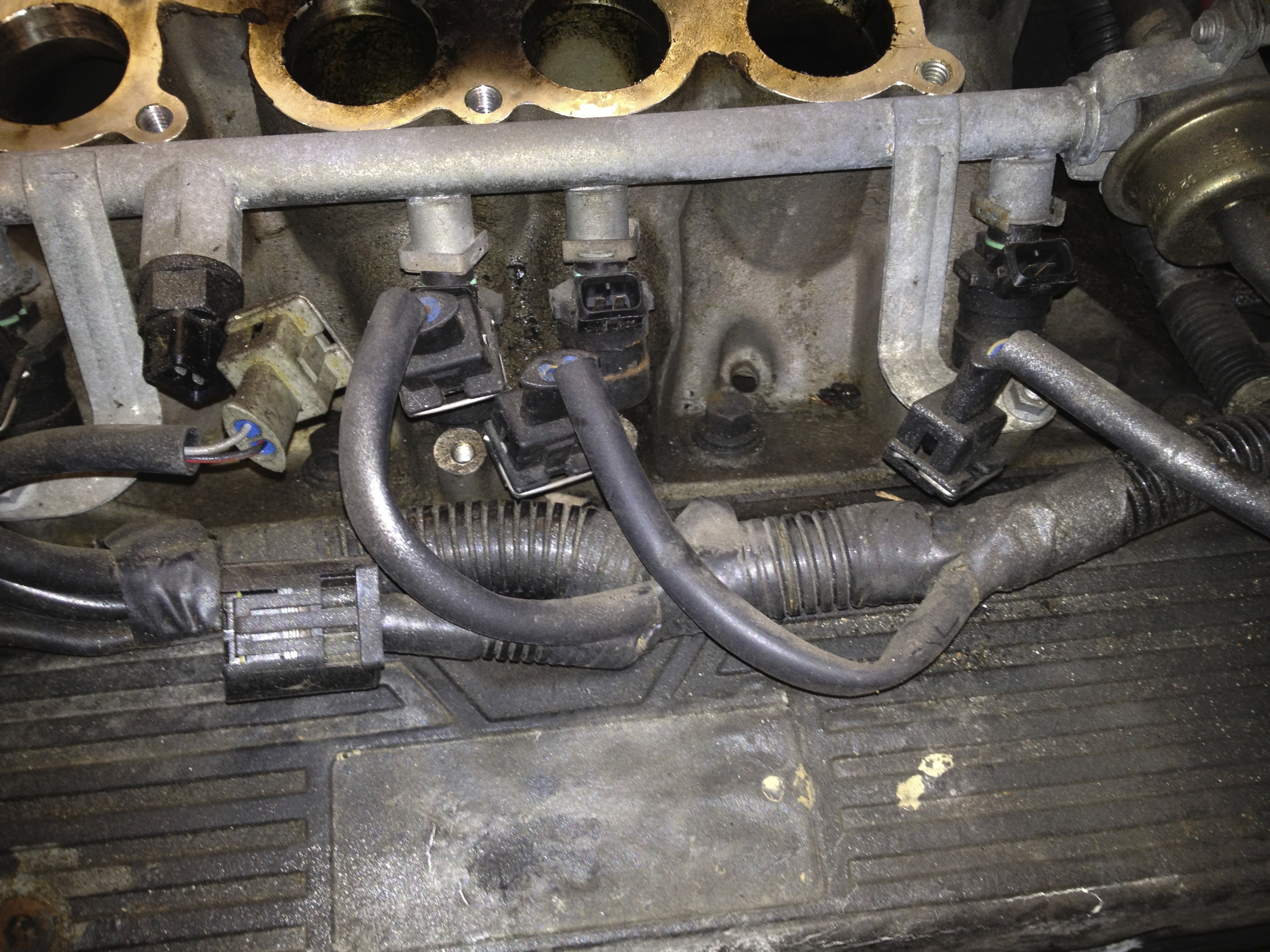 Injector connections removed. Also notice the connection to the fuel rail (white connector) on the left. Directly below that in the picture is the large connection from the loom to the other end of the potentiometer as mentioned above.
You should now have all of the upper near side wiring loom disconnected and free.
On to the off side then.
With the plenum already removed access is already pretty good. The only thing left on the top of the engine are a couple of hoses and the PAS reservoir (if you have PAS of course). This is attached to its own small bracket via a jubilee clip which in turn is bolted to the trumpet base. Undo said bolt and off it comes. I hadn’t drained the PAS fluid at this point and it wasn’t an issue. Just make sure the top of the reservoir is on tight and it shouldn’t leak.
 PAS reservoir attached to trumpet base
There are also 2 vacuum hoses (not filled with any fluid, just air !) that feed into the trumpet base. They emerge from the front wing. These are held on with jubilee clips. Just undo and remove.
 Hoses on trumpet base in the centre of the picture
 The 2 (larger) hoses emerging from the front off side wing. Also note the throttle cable coming out of the wing and disappearing round the back of the engine.
 Hoses removed
Now its the same as the near side, pinch and pull off the injector connections and twist and disconnect the off side lambda probe wiring. That should be it for the upper part of the off side loom.
Follow the loom onwards towards the front of the engine. It will head around the rocker cover, bend around the alternator/tensioner bracket and plunge straight down towards the floor via a p-clip attached to the water pump housing.
 Loom making its way round the alternator bracket
 P-clip in the very middle of the picture with the loom coming in from upper left and exiting straight out to the bottom.
The major parts of this part of the loom are a connection to the front nose wiring loom, an earth connection and wiring to the 100 amp fuse.
Time to get under the car !
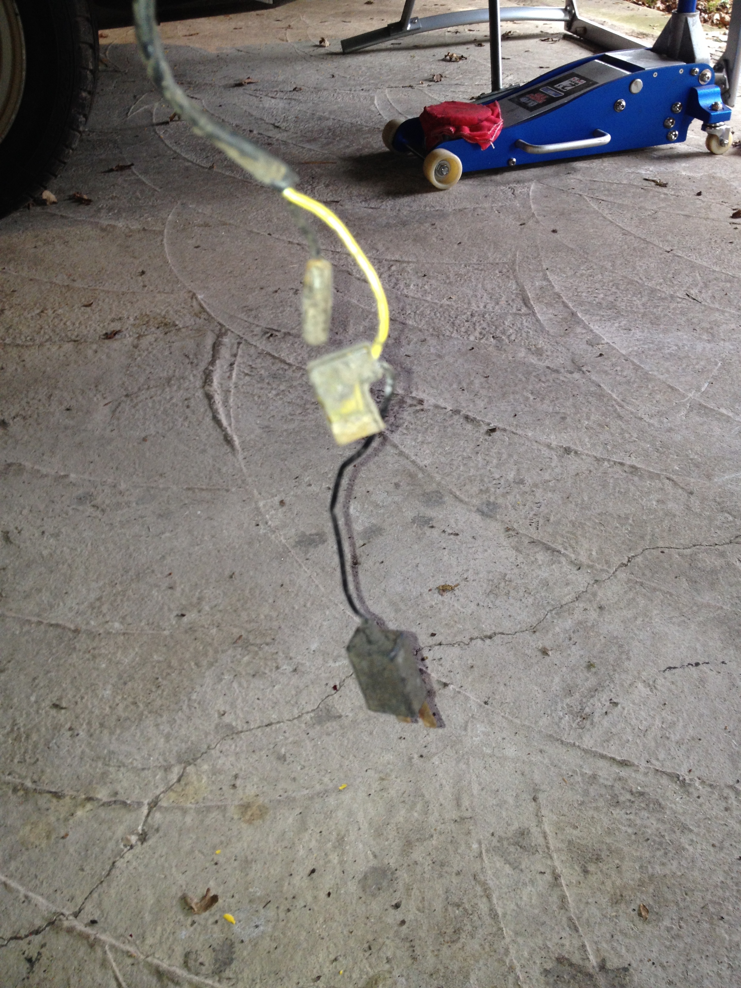
The large brown wire goes from the 100 amp fuse to the earth connection on the engine block. The large connector connects to the front nose loom. The main red cable connects to the front of the started motor. There is then a shorter red cable from the starter motor to the 100 amp fuse.
 Main cable coming in from bottom right to front of starter motor. Smaller cable then from the starter motor to the 100 amp fuse at top left. Zooming in on this picture also shows there is a spade connector to the starter motor as well.
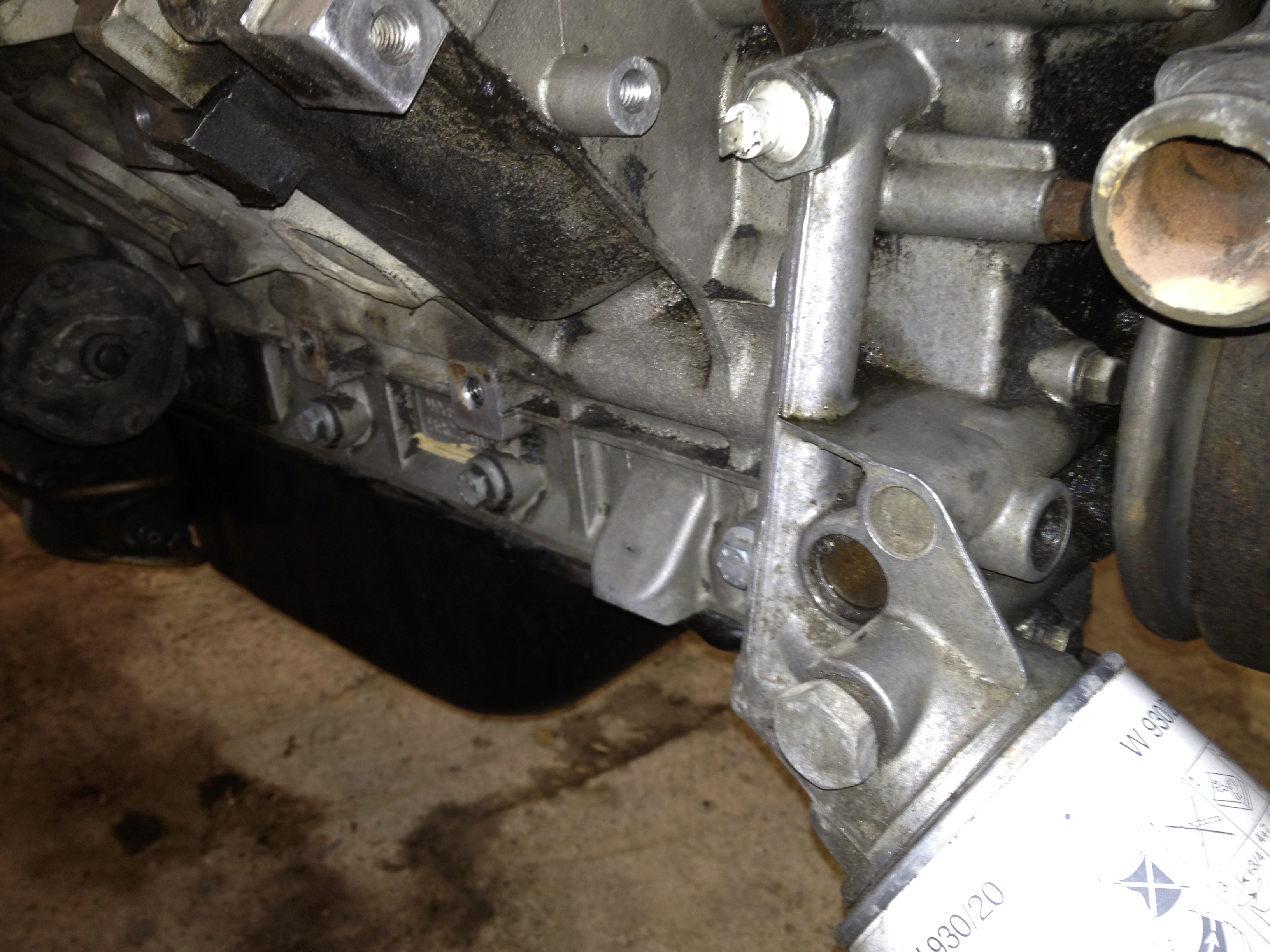
 The 100 amp fuse holder attached to the off side engine mount bracket. Red wire from starter motor coming in from the right. Brown wire exiting to the earth connection on the left.
 This is the best picture I have of the earth connection. It is top centre, in the circular threaded lug, next to the spade connector
 Earth connection bolt described from above (not too sure how much this really helps, but I’ve included it anyway)
Moving towards the front of the car/steering rack you will find the large connection between the main loom and the front loom. The front loom does not have to be removed, but it must be disconnected. It powers the lights, indicators, horn, alarm, carbon canister and washer bottle pump. As far as I remember it also has connections for the oil system/sensors. I will update this asap to confirm (e.g. the below picture).
 Spade connector onto oil transducer. The oil filter is directly to the right with the engine oil sump at the top. This sensor is on the underneath of the engine block.
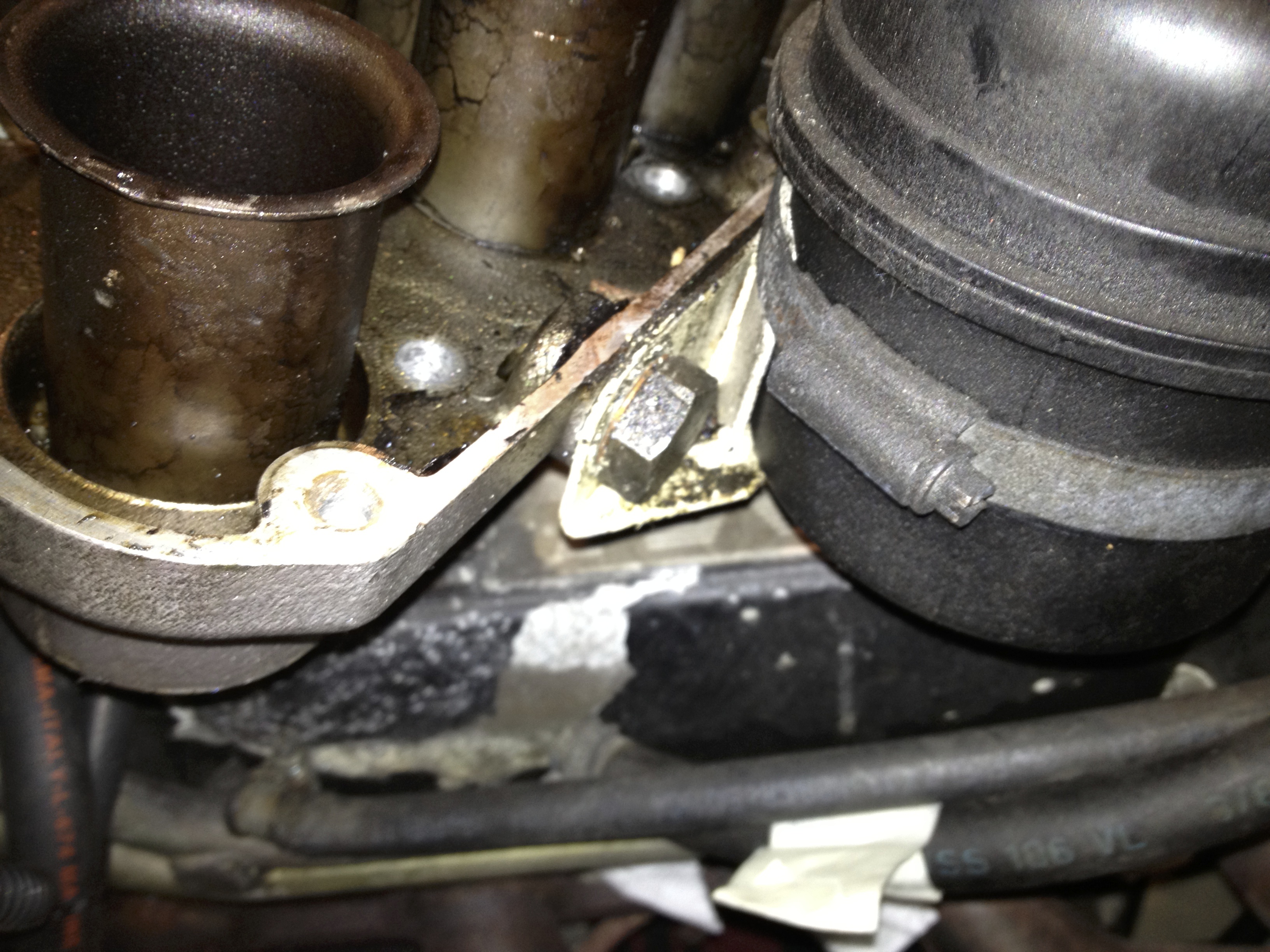
Finally moving over to the near side again but still under the car, there is one last earth connection. This is under/next to the rearmost exhaust port.
 Above mentioned earth connection just left of centre
There we are then. That should be all of the engine bay wiring loom disconnected. There may be a couple of random connections that I’ve forgotten about but nothing major. The main point is noting where is all goes. Easiest is to physically attach tape to the ends of all the little random looking spade connectors and write where they connect to.
Our last stop on the wiring is the gearbox and handbrake switch. These simply pull off as a connection on the gearbox and 2 spade connectors on the handbrake. You need to be under the car pretty much right in the middle and if you look up you should see the following.
 Connection on the gearbox on the near side (large black cap on left)
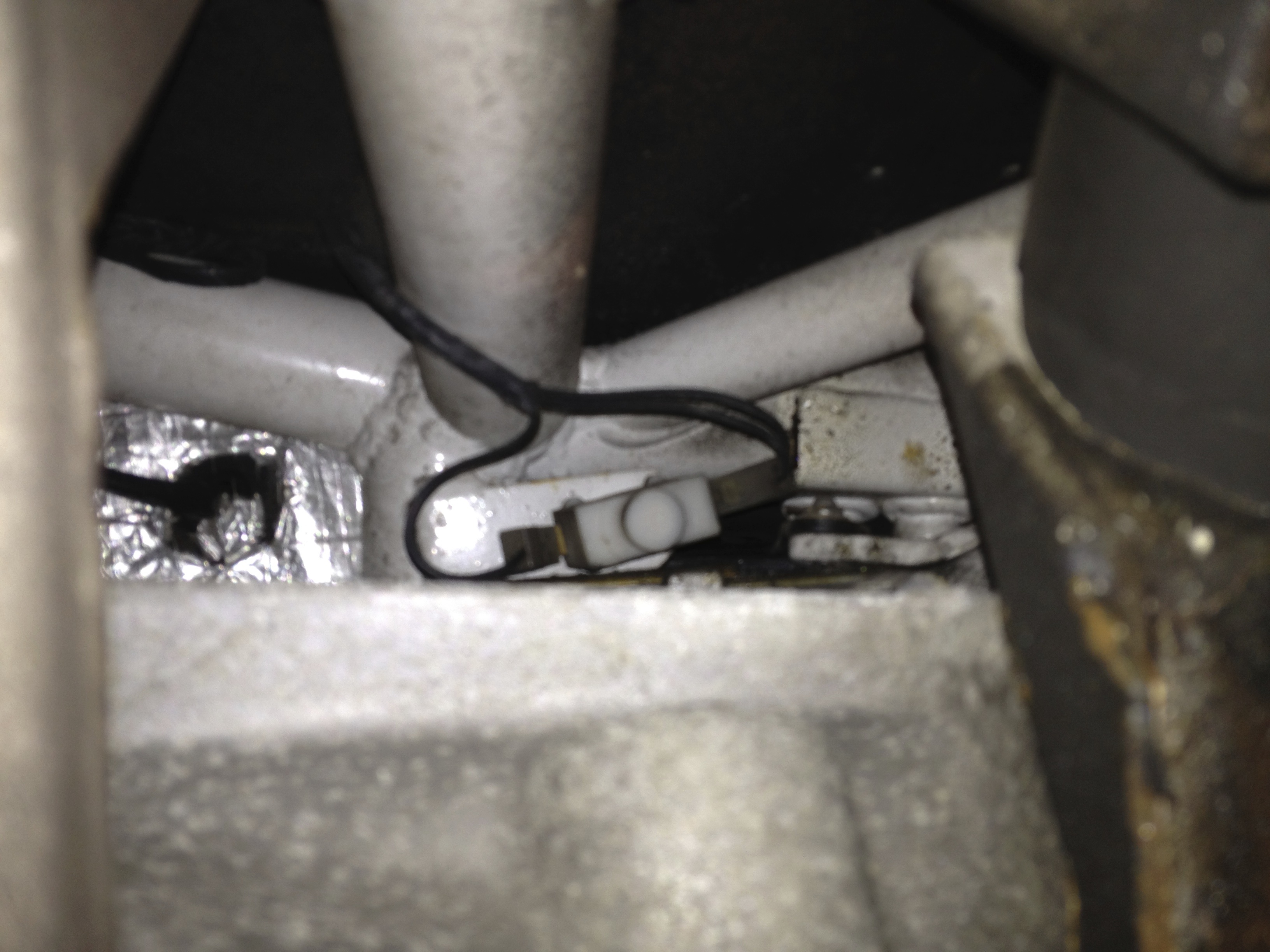 Spade connections on the handbrake switch, again on the near side
Moving on then, lets put a stop to things. Thats right … brakes.
Bleeding the brakes is a pretty simple process. Starting with the caliper furthest from the master cylinder (rear near side) place some rubber/plastic tubing over the end of the caliper bleed nipple. Crack the nipple open and place the other end of the tube into a container of your choice (but preferably something that can be resealed. This will aid in the disposal of the fluid later which needs to be done in the correct manner at the correct facility). Next, undo the cap on the brake fluid reservoir in the engine bay. Its half way along the off side wing. Don’t fully remove the cap, we are just trying to ensure there isn’t a vacuum in the system which will make bleeding the brakes easier. Then get into the car and start pumping the brake pedal until no more fluid comes out. Move around the car doing this for all 4 calipers until nothing else comes out. The brake pedal should also be on the floor now with no resistence. Now bleed the clutch. Very similar to the brakes. There is a bleed nipple on the clutch slave cylinder which is next to the starter motor on the lower off side of the engine. Just keep pumping the clutch pedal until there is no more resistence.
Brake fluid reservoir at bottom left with the yellow topped cap
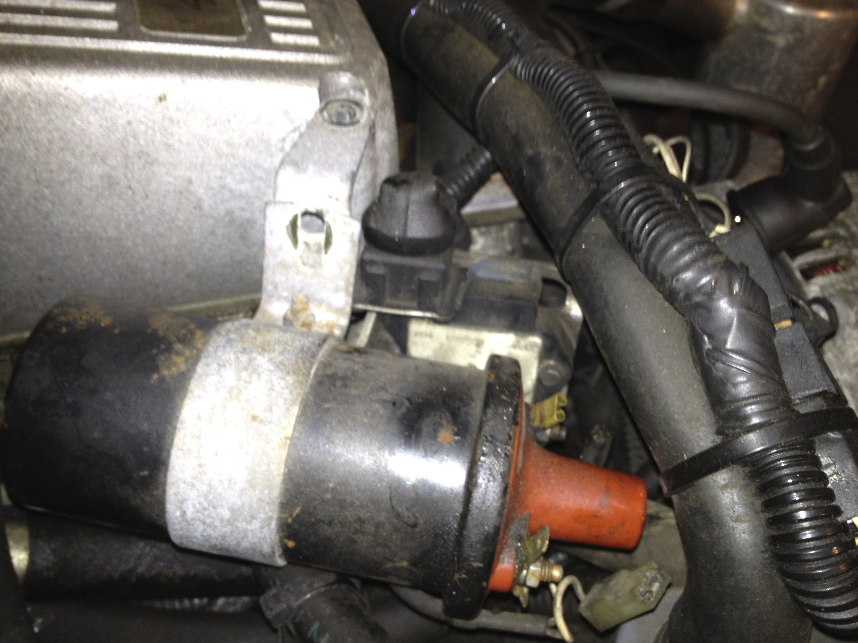
 Clutch slave cylinder at centre right of picture. The copper clutch pipe can clearly be seen and the bleed nipple is directly to the left of where the copper pipe enters the cylinder
Now move into the engine bay and high up on the off side wing towards the rear is the bulkhead block where the pipes (brake and clutch) all meet up. The top 2 are for the front brakes, one pipe per caliper. The 3rd pipe down is for the rear brakes. This pipe goes through the brake balance valve above/next to the differential and then splits via a 3 way union to each rear caliper. The bottom pipe is for the clutch. Unscrew the 4 male unions from the bulkhead block and thats it.
 The bulkhead block with the male unions screwed into it can be see towards the left of centre.
On to the fuel pipes/system. There are 2 connections that need removing in the engine bay (the feed and return from the fuel rail) and from the tank to the pump at the rear. The carbon canister hose also needs to be disconnected.
The 2 engine bay pipes are easy. Just undo the hose clamps and thats it. Be prepared as you may lose a little fuel.
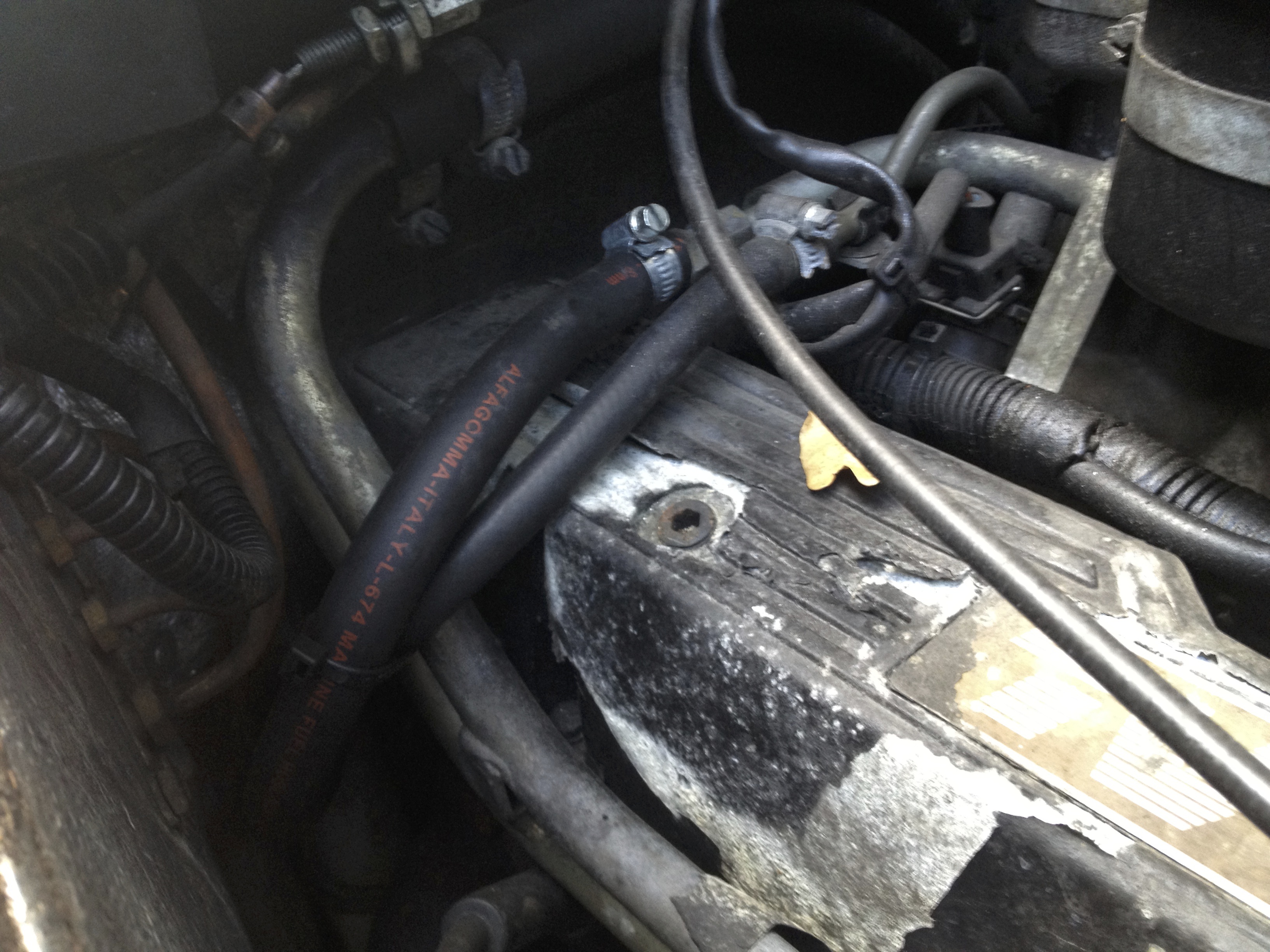
 The 2 fuel pipes in the engine bay (hoses with red writing on them)
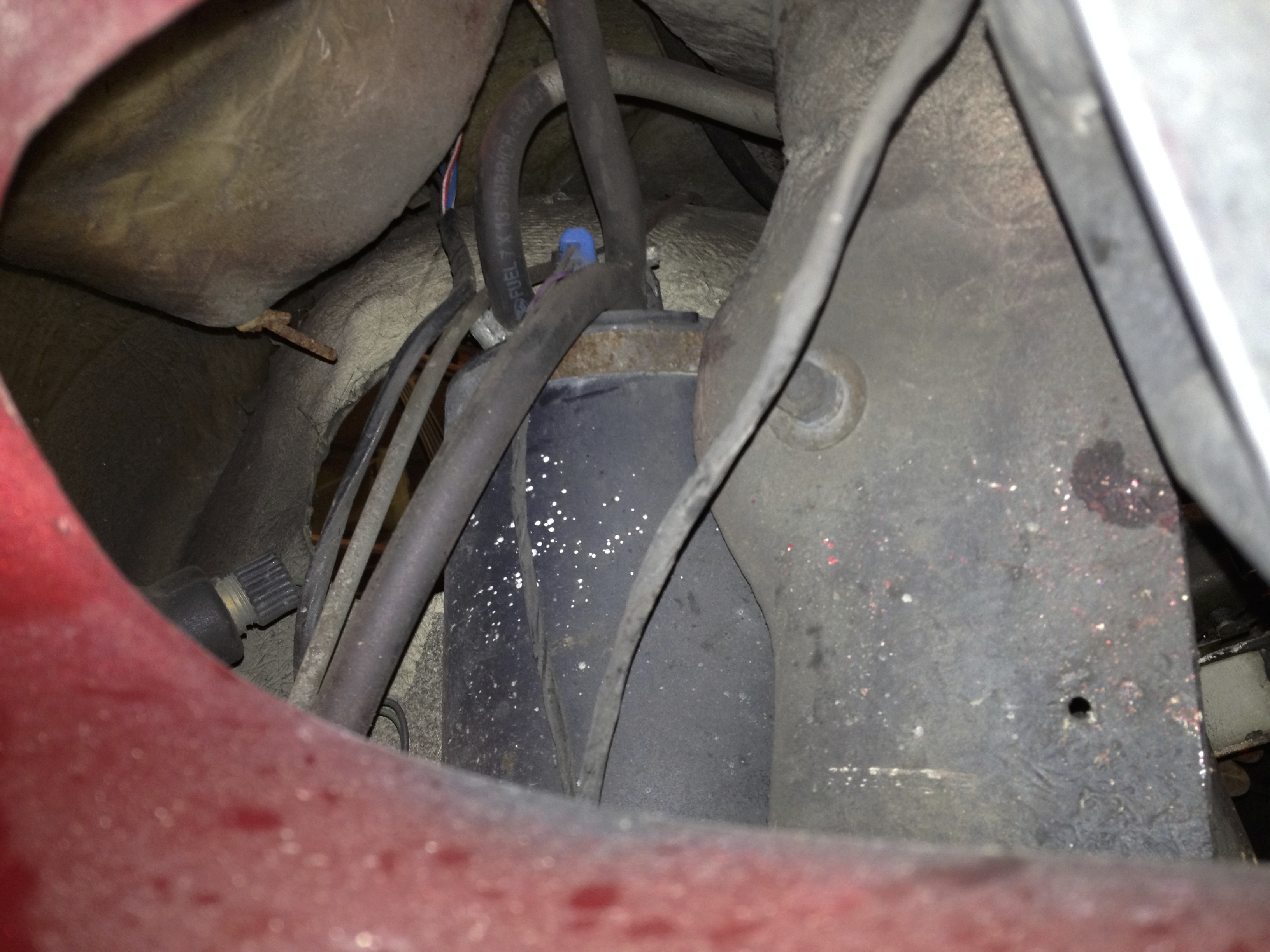
At the rear of the car now on the near side. The fuel pump lives attached to the side of the chassis in the middle of the 2 lower wishbone mounts. Undo the hose clamp at the rear of the pump and remove the hose.
 Hose disconnected from the pump
Whilst here its worth mentioning that there is another electrical connection for the pump that can be removed. The pump has 2 terminals, so remove each connection and there is also a 3rd connection that appears to be an earth/ground to the chassis. This is clamped to the chassis via the upper pump mount. Slacken off the top fuel pump mount nut and remove this earth connection.
 Electrical connections to fuel pump. 2 spade connectors and the earth at the bottom
The carbon canister lives inside the very front of the off side wing. What does it do ? Well its clearly where carbons go to be canistered of course ! Actually its allows fuel vapours from the tank at the back of the car to be burnt off harmlessly by feeding them back into the engine to join in with the combustion process.
The canister is connected to the fuel tank by a long rubber hose that emerges out of the front wing at the very bottom, snakes its way across the front of the engine bay and then down the length of the car along the near side of the main chassis backbone. Getting to the canister is a little tricky. The inspection hatch in the off side front wheel arch needs to be removed (this is what you change head light and indicator bulbs through). The hatch cover is held on with a couple of self tapping screws (at top and bottom) and lots of sealant. Remove the screws and prise the cover away carefully. You will immediately see the canister in front of you through the hatch. It is held in position by a jubilee clip that has a thread on it that emerges into the wheel arch. Undo the bolt in the wheel arch and the canister is free to move. I then found the easiest way to identify the correct hose (there are a couple connected to the canister) was to reach in through the front grill of the car (this can be tricky if you have large hands/arms. Sorry, but this is the way I did it so I’m unsure of other methods). You are trying to find the hose on the floor just to the left of the radiator opening. Follow this up and around to the top of the canister and remove it (it may be held on with a jubilee clip). If its on too tight then don’t panic. Just a little more work is required as you will need to remove the canister to access to the jubilee clip. There should be enough slack to pull it out through the radiator opening. Once disconnected, pull the hose out from the engine bay side.
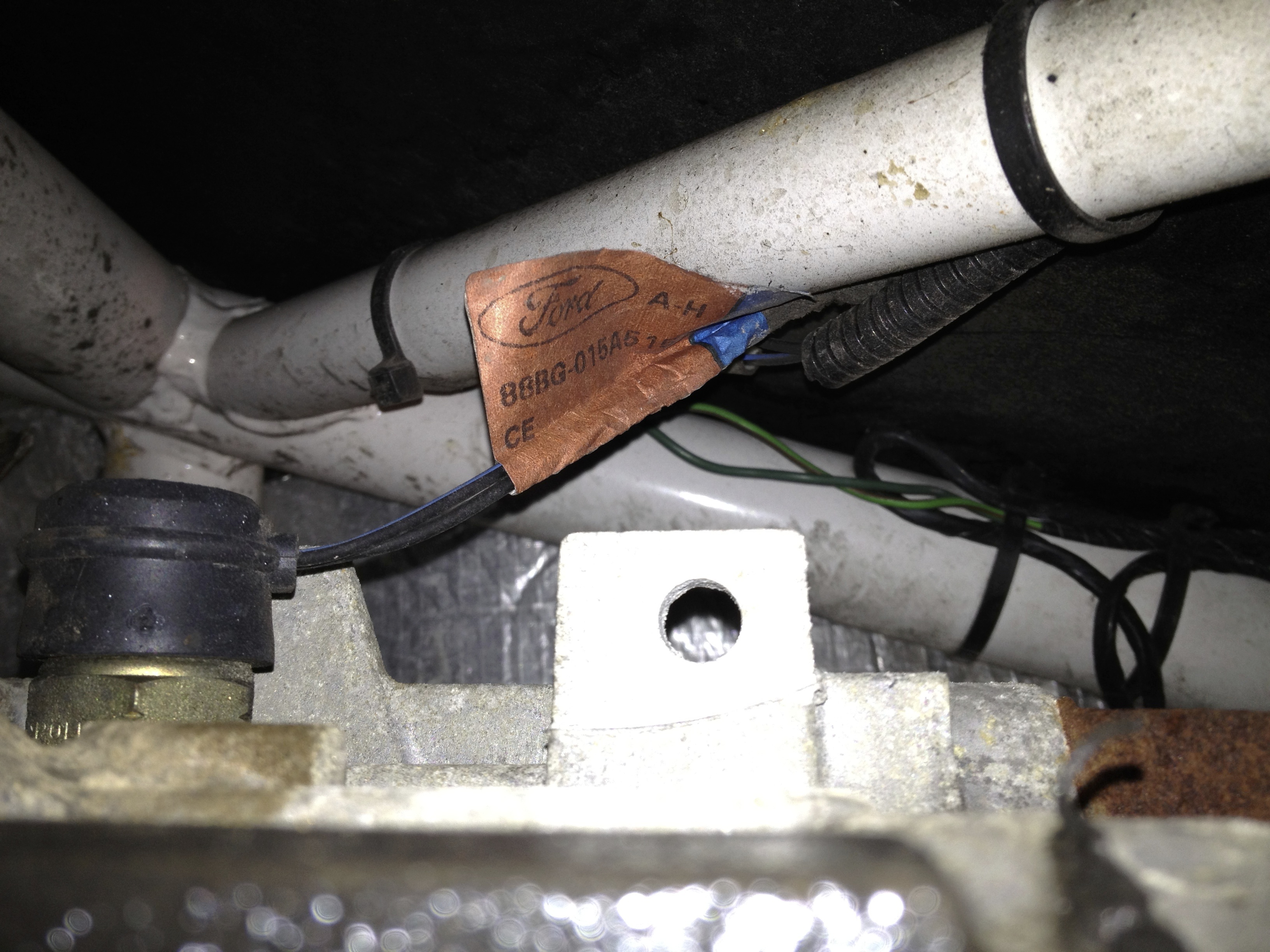
 Inspection hatch removed. The canister can be seen on the left with the jubilee clip around the top of it. Also notice the thread just to the left of the hatch with the nut still attached securing the canister to the wing
 Bottom of the canister can be seen hanging down from above. You can also make out the hose you need as the large hose on the left hand side with just a hint of over spray on it, beginning to bend back to the right at the bottom and thus heading towards the engine bay
 Looking up towards the top of the canister with the relevant hose coming up from the lower left
 Jubilee nut removed and the canister pulled out into the engine bay. The hose is the bottom one of the two hoses together in the middle of the canister
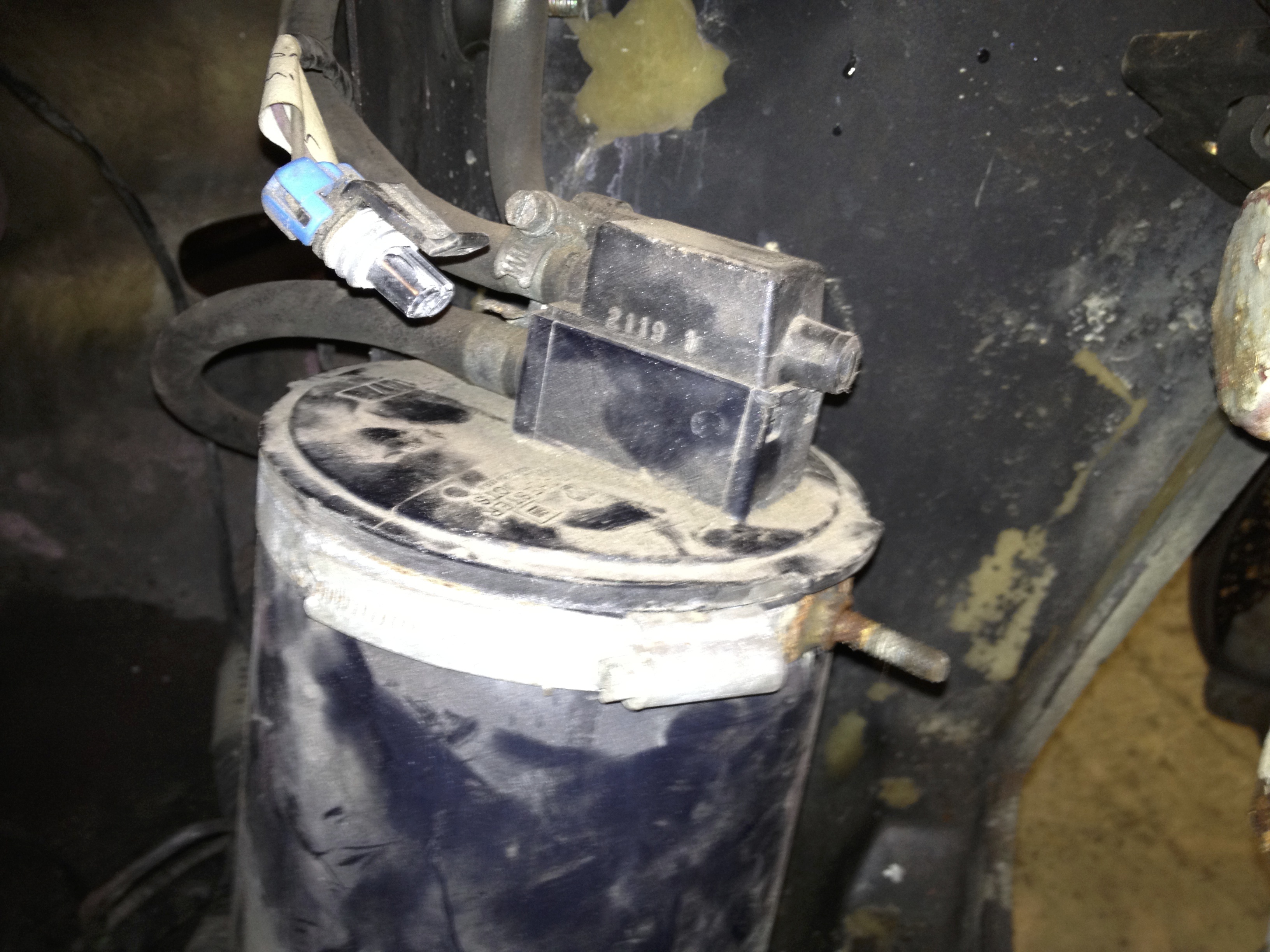 Another view of the hose. Its the lowest one bending off down to the left
Water pipes next. Access is a little annoying here, but all in pretty simple again. The 2 pipes attach to the heater rail, which in turn is attached to the off side head. Again, just undo the hose clamps and remove the hoses (potentially more coolant loss here).
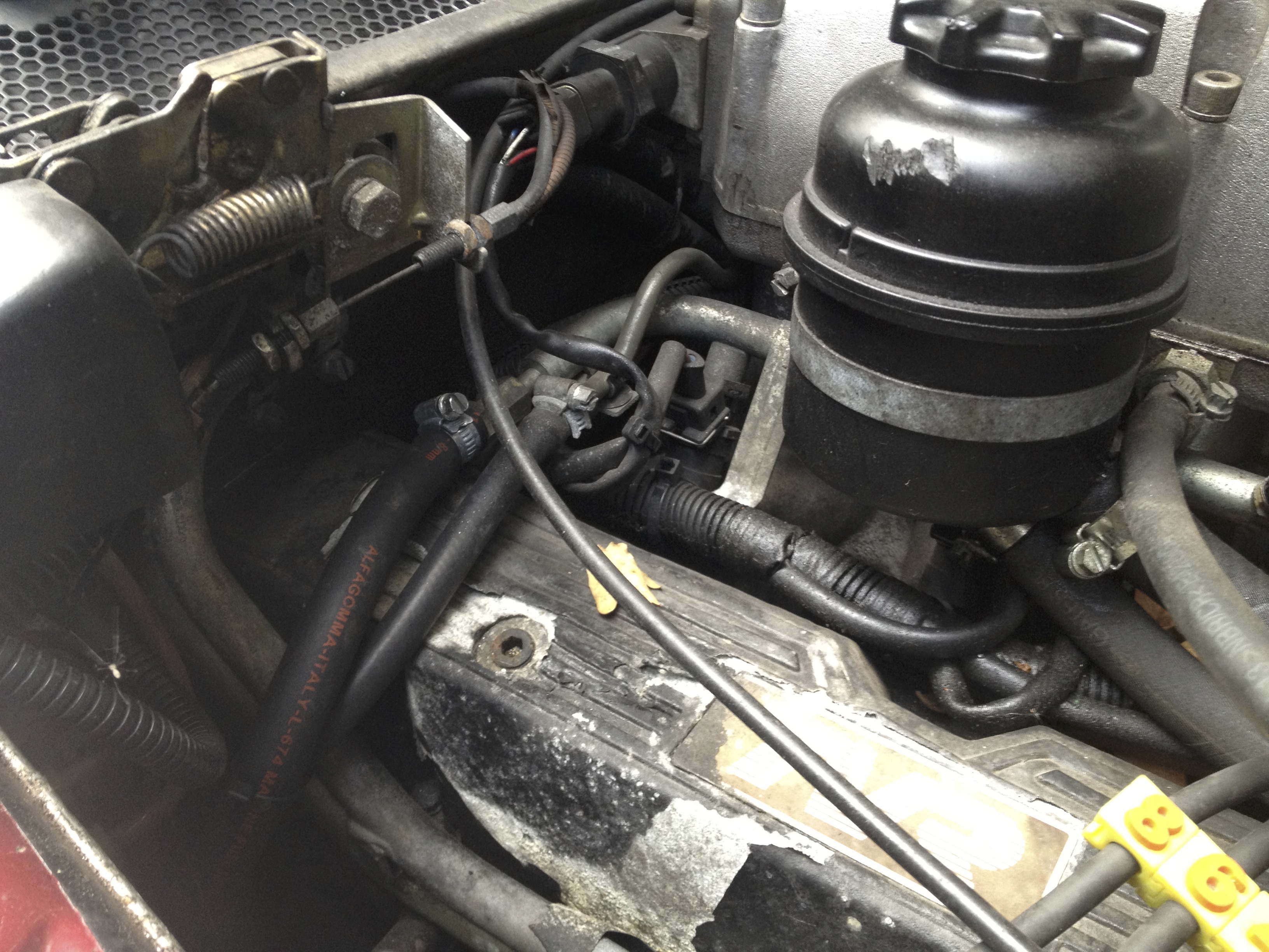
 Same picture as above, but now looking at the heater hoses in the upper left, almost in the shadows. You can just see the 2 jubilee clips next to each other
The handbrake can be slackened as per almost every other handbrake on any other car. The adjuster is in an awkward place though. It sits just above the front of the diff on the off side. Slacken this off by turning the rearmost knob. Penetrating fluid/WD-40 is your friend here as its normal for the 2 knobs to be very tight to each other. Plus you are trying to unscrew the rear knob along what is normally a very dirty cable. Lubrication will help things enormously.
 The adjuster can just about be seen here, centre right of picture, right above the drive shaft. Also notice the brake bias valve (mentioned above) above the flexible brake pipe.
 Further view of the adjuster from above (although you won’t have this view yet of course)
Finally, we’ve made it to the last objective. Bleeding and removing the PAS pipes at the rack. The high pressure hose from the pump to the rack is a banjo bolt fitting. Simply undo and remove the bolt. The low pressure hose back to the reservoir is a push fit with a jubilee clip. Again, undo and remove. Just let the fluid drain out.
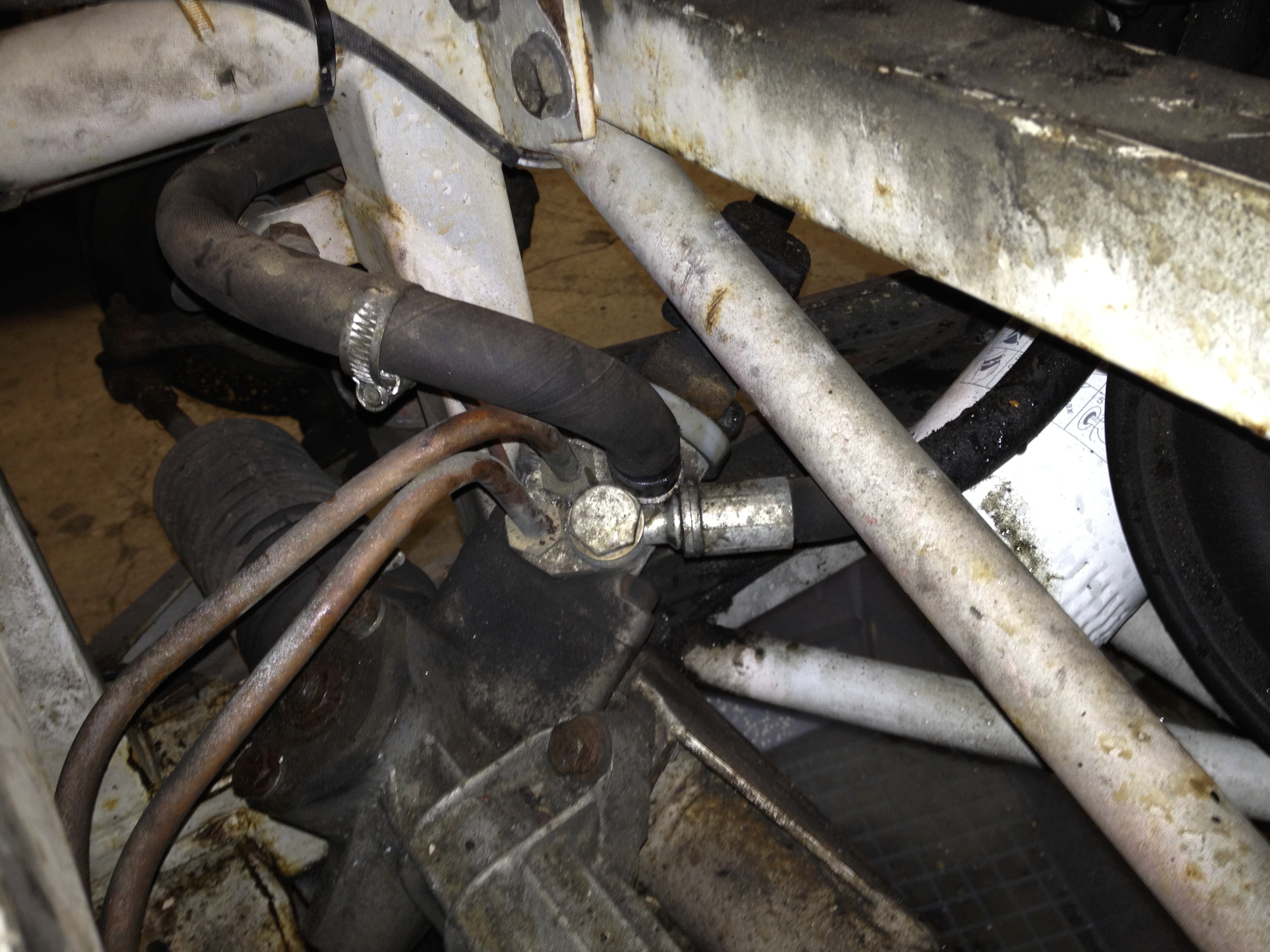 These are the 2 PAS connections on the steering rack that need to be undone (the black hoses NOT the copper pipes)
Thats it. Everything major is disconnected and its time to raise the body !
Not quite. The last thing to do is crawl as best you can over every last inch of the chassis and remove all the cable ties. There will be more than you can possibly imagine. No matter what they are supporting its worth removing them all as they are pretty cheap to replace and this way you should guarantee nothing is caught as the body is lifted.
