Right then, moving on at pace, what course of action am I going to take ? Hmm…
Well for me, nothing less than a total overhaul was on the cards. Despite the vastly increased costs and time it was an easy decision. I’m a firm believer of if you’re going to do something then do it properly. It would have been very easy for me to put all the ancillaries back on after cleaning up the chassis and then call it a day. But no. Funnily enough this is actually a very common way to go. Seeing as you have such great access to everything it makes sense to replace replace replace.
The following is a list of what I wanted to change/replace:
- Upper and lower ball joints
- Track rod ends
- All coolant hoses
- Complete fuel pipe overhaul (including all copper pipes and rubber hoses)
- All engine bay heat shielding
- PAS hoses
- Suspension bushes
- Diff bushes
- All CV joints and boot covers
- Handbrake cable
- Complete brake pipe overhaul (including all copper pipes as well as new braided hoses)
- Refurb rear brakes
- Upgraded front brakes
- Pretty much every bolt, set screw, nut and washer I can get to
I’m sure there are more things but thats all I can remember at the moment. I’ll update this as and when I realise/remember.
Thats quite a list isn’t it. Oh well, time to ask for some more overtime at work to help with the finances…
Along with the above, everything (and I mean everything) will get cleaned, painted, re-covered, wiped down or re-greased. My aim is to leave as little as possible untouched. Guess time will tell on how that goes.
Firstly though its time to inspect the chassis as it came out from under the car and see what we’re dealing with. I was tempted to have the chassis completely shot blasted and re-powdercoated regardless but its not the cheapest thing to do. Ultimately the decision was made for me by good old mother nature. Whoever invented the concept of oxsidisation is a **** ! If only things didn’t rust eh. But they do and there were 2 small areas on my outriggers that meant a full chassis refurb was on.
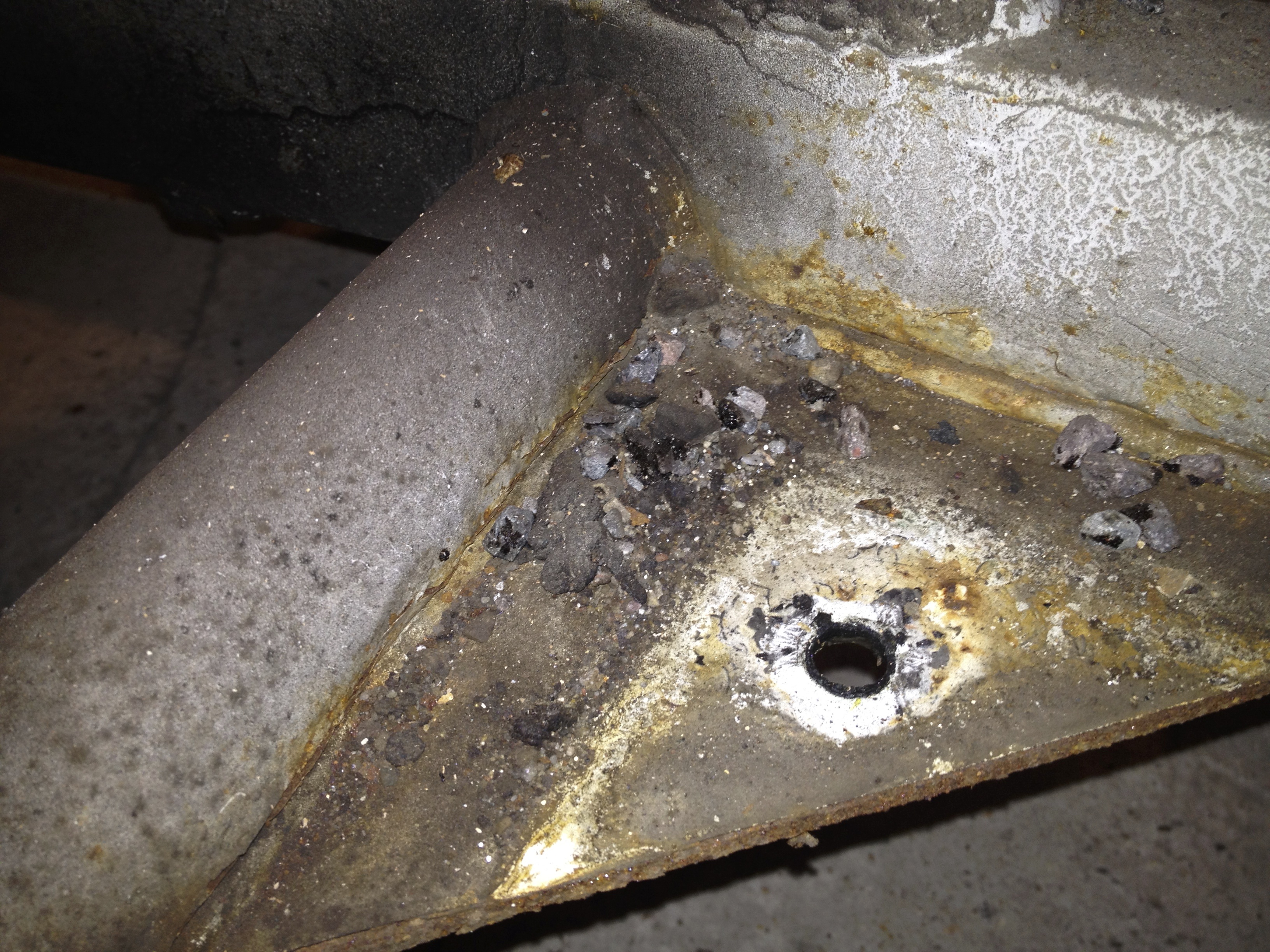
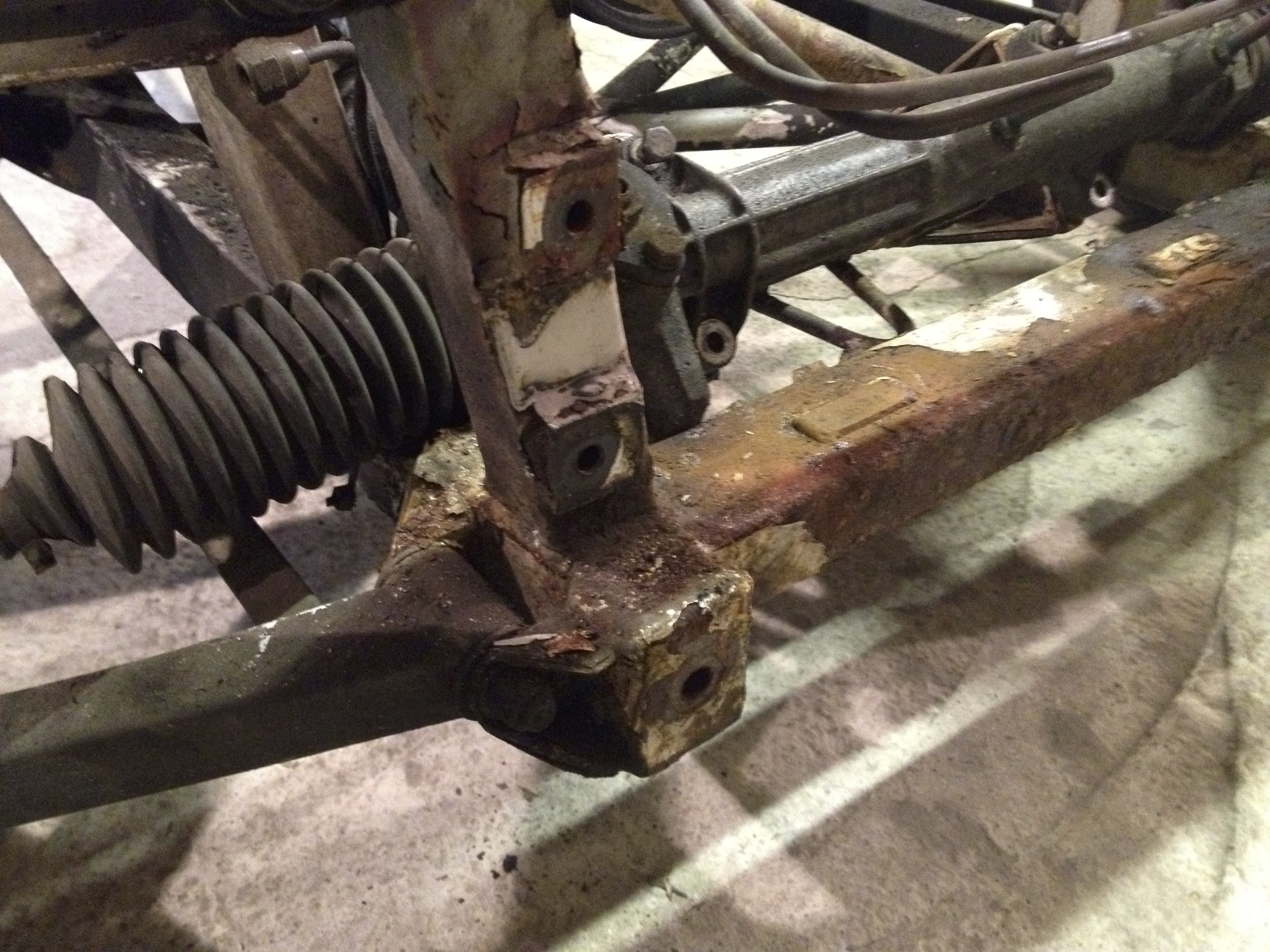
The first hole was just about large enough to get my hand into. It was on the rear most near side outrigger. The other hole was very small, barely able to get a finger into, on the opposite side at the front off side outrigger. The below picture shows the larger hole (apologies I didn’t get a shot of the smaller hole).
 Note: the vertical plate with the hole in it is where the seat belt reel bolt attaches to the chassis after passing through the body
For reference the piece of putty covering the left side of the hole is just larger that a £2 coin (perhaps 3cm for those of you who may not use £). In a very perverse way I was sort of disappointed in how good the outriggers were. I know that sounds strange, but to go through all that work to find a couple of small holes seemed a bit anticlimactic. In a way i’d have rather lifted the body and had pieces falling out all over the floor (there are other body off write-ups that show this, I’m not exaggerating). At least then I’d have known for sure that I took the correct decision. Then again, other than the 2 holes the rest of the chassis was in remarkably good condition. Especially for a later car which aren’t well know for their quality of factory powdercoating.
The following are some general shots of the chassis state. Yes, its very dirty in places and there is a bit of surface rust, but its really in very good nick.


Other than the outrigger holes the only other area of concern was the front cross member. This is the very forward most lower bar that runs across the car, pictured below.
Not looking too good is it. No real way of telling how bad it is until the shot blasting has taken place.
I have agreed for a well respected TVR specialist, Str8six, to handle the outrigger replacement. Welding is just something I know nothing about and there was no way I was going to attempt this myself. Str8six were very accommodating on negotiating with me on costs as of course i’d done a huge amount of the labour myself. They agreed to pick the car up as a ‘rolling chassis’ and then then return it after the work was completed. As far as I understand it they are going to strip the last parts of the chassis down (wishbones, shocks and steering rack) and then ship everything just up the road to Willow Sports Cars who actually do the shot blasting and powdercoating. (If this is actually incorrect I apologise. Please let me know and I’ll correct this immediately).
Once back from shot blasting and powdercoating I arranged for them to build it back up to a rolling chassis again with the wishbones now on polybushes. What I wasn’t expecting was it to come back with the steering rack having been cleaned, the front hubs cleaned and re-painted and not just powdercoated but new rear toe adjusters. All in all, a massive thanks and thumbs up to Willow Sports Cars and especially Str8six.
(re the above 2 paragraphs, a hugely important thing for me is the fact I also have a nice invoice, from one of the most well respected TVR specialists there is, for the work done. I know I’ll never recoup all of my costs, but that invoice should help in getting some of it back, hopefully, if I ever come to sell. But most importantly it also proves that the crucial chassis work has been done properly by an expert)
So in no particular order then I need to get the following done before the chassis is collected for its long weekend away at the spa !
- Remove engine
- Remove gearbox
- Remove prop shaft
- Remove diff
- Remove all brake calipers
- Remove all brake and fuel copper piping
- Remove front anti roll bar
Those are the main things and I’ll also talk about everything else as we go along.
I started with the largest object (and most expensive thing if it were to go wrong…gulp). The engine. In fact I decided to remove the engine and gearbox as one entire unit. A second pair of hands in a helper is a must here in my opinion. Its not actually as critical as putting the engine back in, as on removal it doesn’t matter too much if you dink the chassis here and there as its getting refurbed anyway. But there is no way I’d want to do this on my own.
So off to machine mart I went and ordered a nice new engine hoist. Yes I could have rented it, but now I have one forever (plus in the future I’m very keen on possibly building an Ultima, so it will get used again…a promise I’ve made myself and just have to keep).
There isn’t a huge amount to do amazingly. The remote mechanism for the gear change has to be removed, the gearbox mounts have to be unbolted, the engine mounts unbolted and the near side mount removed and thats about it actually. The remote mechanism is necessary as the lever in the car isn’t actually in line with the input to the box.
The above picture shows the remote linkage, top of frame. It connects to a rose joint on the top of the bell housing, the gear lever you use in the car at the middle and to the actual gearbox at the back.
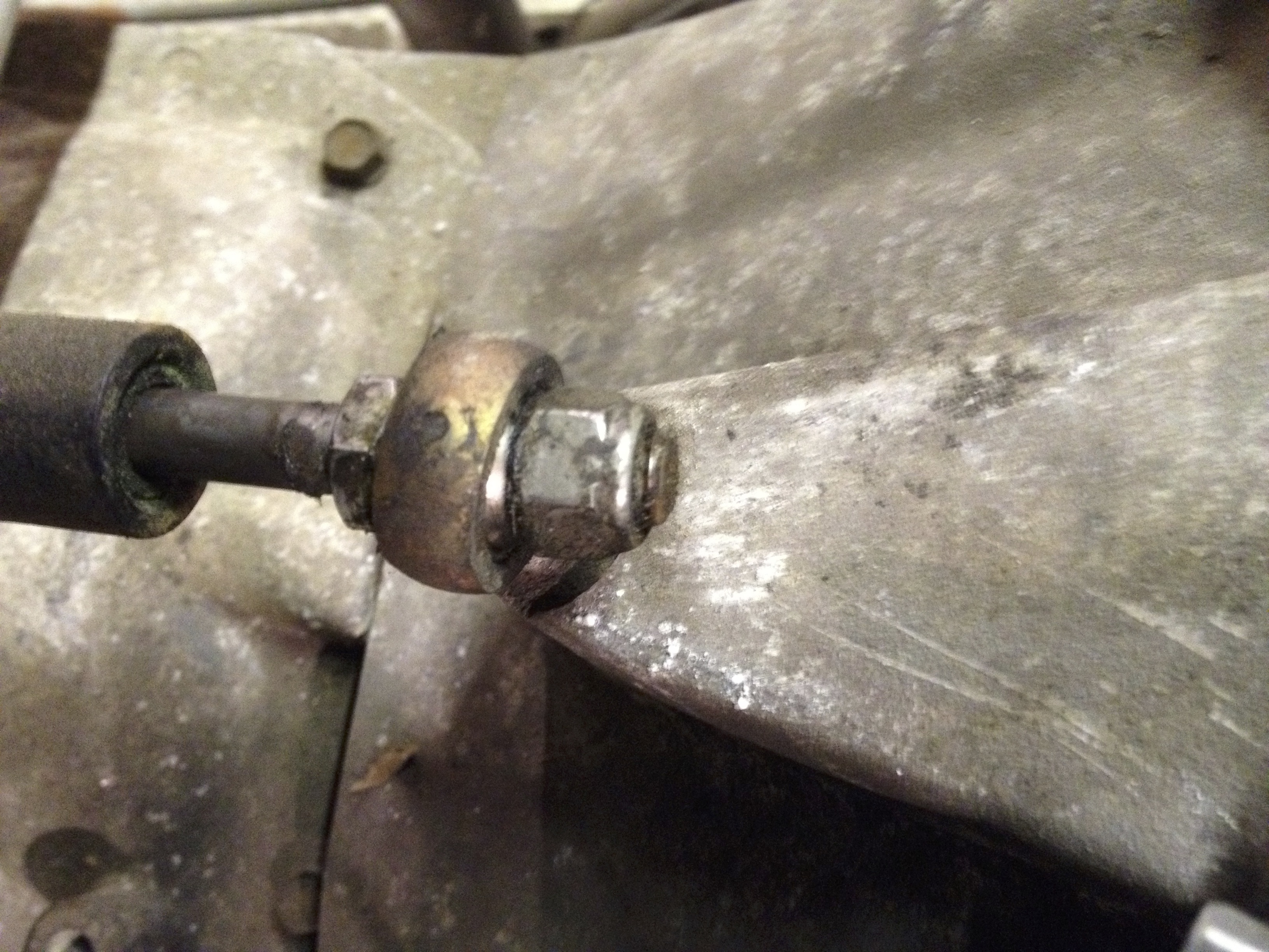 Front remote connection. Just a simple nut to remove.
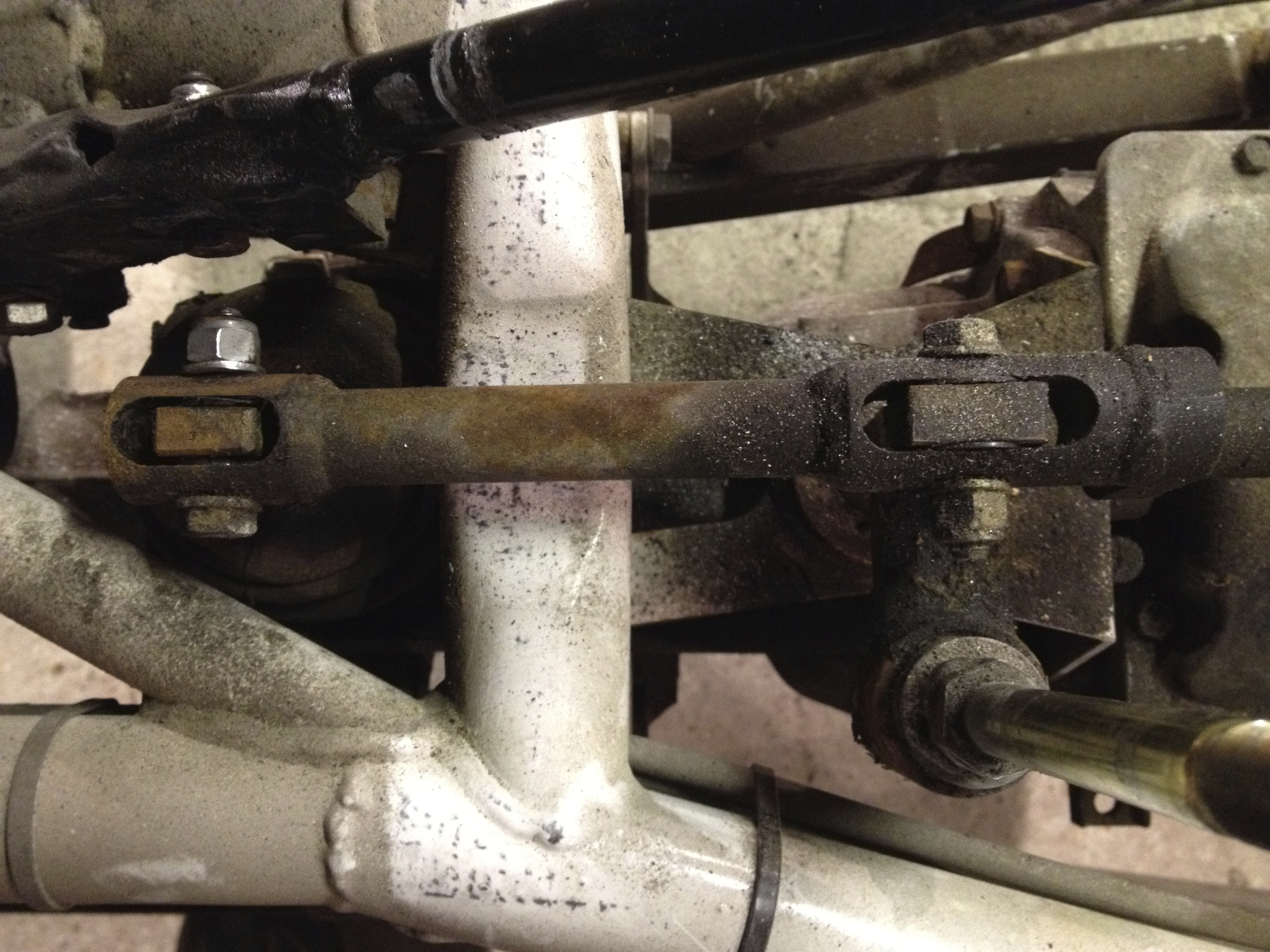 The 2 rear remote linkage connections
When removing the 2 rear bolts be aware that there is a plastic bushing running the entire length that the bolts slide through. These will need to be drifted out carefully. There are also a couple of large plastic washers between the interior face of the linkage and the gear lever and then the same for the rear most bolt as well. I hope that makes sense. If I can think of a better way to describe it then I’ll update this.
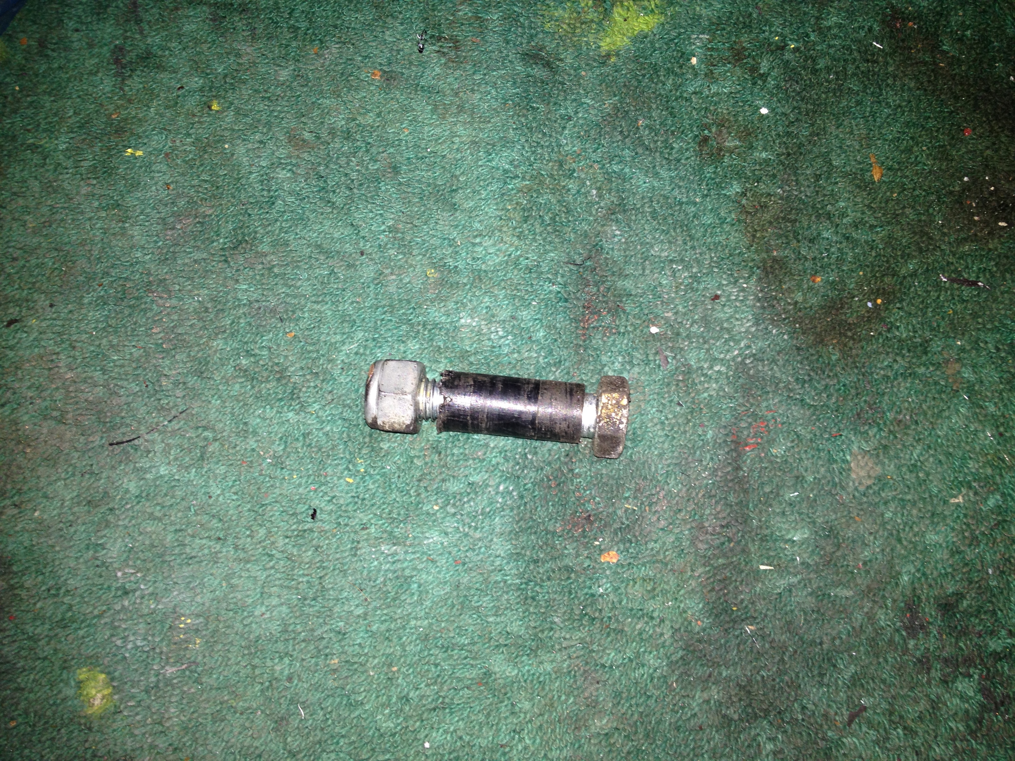 This how the bush looks when removed. Try to imagine this inside the remote linkage and gearbox/gear lever connections
 Linkage removed
The gear lever just pulls out of its bearing. It may be tight but there isn’t actually anything holding it in.
Next up I removed/disconnected the gearbox mounts and the sort of safety cross member for the gearbox… Not actually sure what you’d call it, but it looks like its there to catch the gearbox incase the mounts fail and it drops. The mounts are large rubber cylinders which have a treaded section emerging from each end. Its just a simple nut at either end, although a little fiddly to get to. The support cross member has 2 bolts on either side securing it to the chassis. About as easy as it gets.
 Support cross member in the middle of the picture clearly bolted to chassis
 Rubber gearbox mounts just left of centre
Sadly I don’t appear to have any photos of the engine mounts in situ. The main bracket attaches to the engine block via 3 bolts, 2 at the bottom and 1 at the top. The engine mounting rubber then attaches to the bracket via 2 bolts and to the chassis via 2 more bolts. I’ll try and explain this better later on when we get to the cleaning and painting of parts section. The above is identical for both sides, except there is a spacer between the bracket and mounting rubber on the off side (again, can better explain this later when cleaning and painting).
Also needing removal is the engine bay cross member. As mentioned in an earlier section this is the support bar running across the engine that the swirl pot sits on. 2 bolts on each side and it comes out. Simple once more.
Now everything is disconnected its time to hoist the engine out. It would have been much easier using a load leveller, but i didn’t have one. The below is the arrangement I came up with. I looped a strap under the front part of the engine block just in front of the oil sump and a second strap around the bell housing/gearbox. As you lift the engine out and forwards the prop shaft will just slide out, it isn’t secured in any way.

The actual act of removing the engine is of course up to you. It seems you just have to inch forward and upwards slowly.
Big relief then, the engine is out !
Lets try the diff and prop.
The prop is now already loose at the gearbox end and simply has 4 bolts at the diff end. Access can be awkward but its doable. Just undo the bolts and the prop will drop out.
 3 of the bolts/nuts are seen in the centre of the picture. The 4th is on the other side
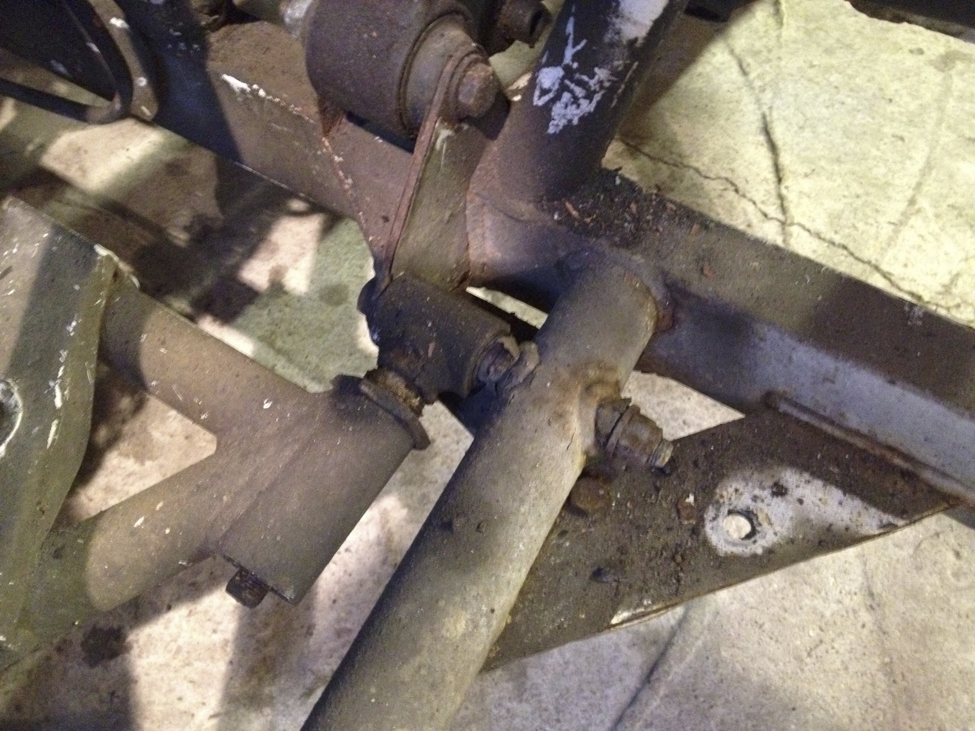
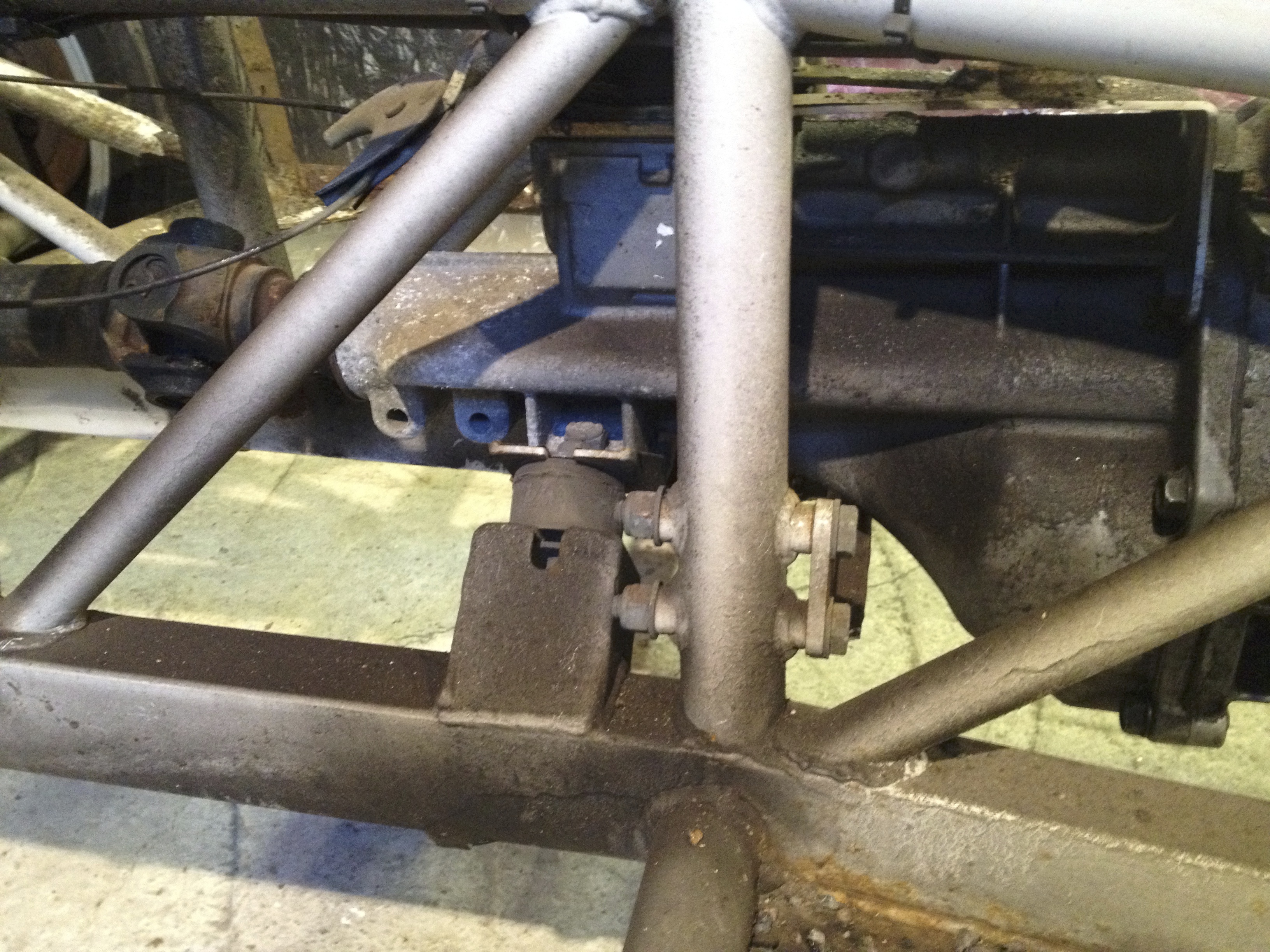
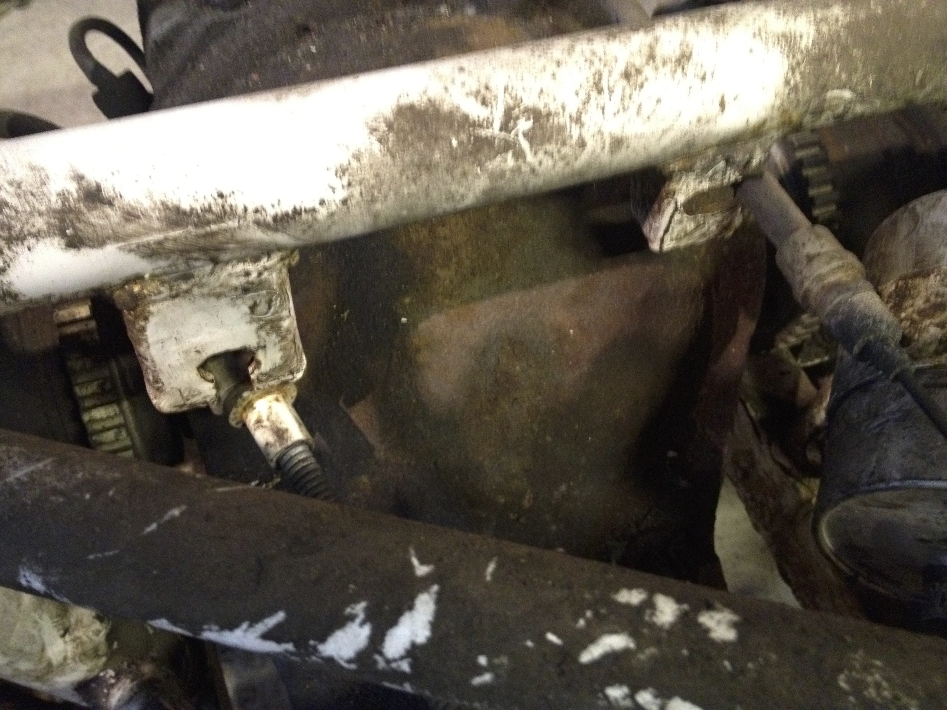
Now the diff. This is tough. Not only is the diff heavy, but it needs to be twisted through 90 degrees and then dropped out of the bottom of the chassis. The diff has 2 forward mounting plates/brackets with 2 bolts each and a mounting bracket at the rear near the top. The above picture actually shows the near side forward plate. The large rubber mount to the chassis is at the very bottom of the picture. You can also see the 2 top mounting allen headed bolts just up and to the right of the prop bolts. These are torqued quite strongly, but should’t be an issue removing (still using the penetrating fluid to help release rusty bolts, yes ? Good).
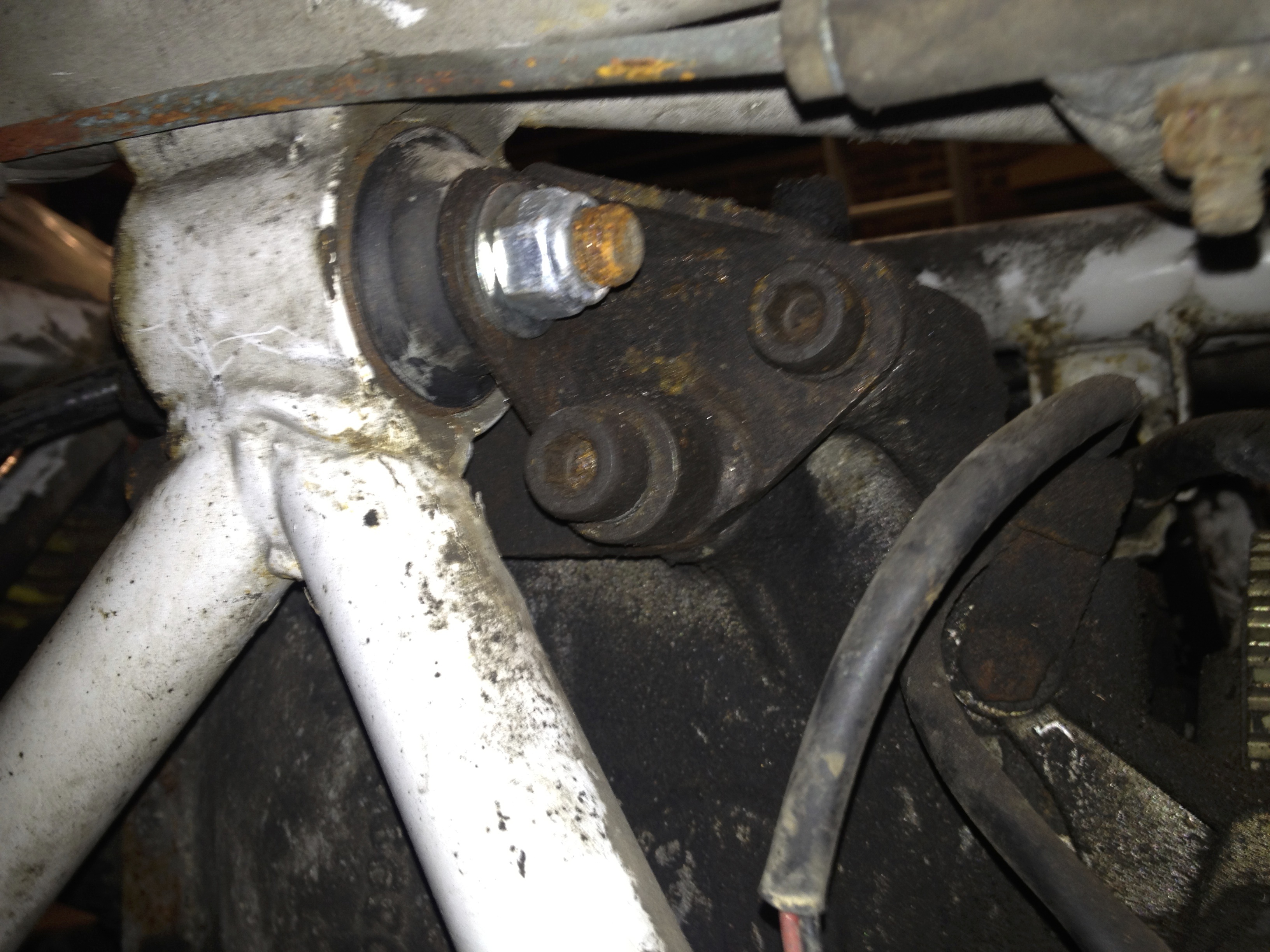
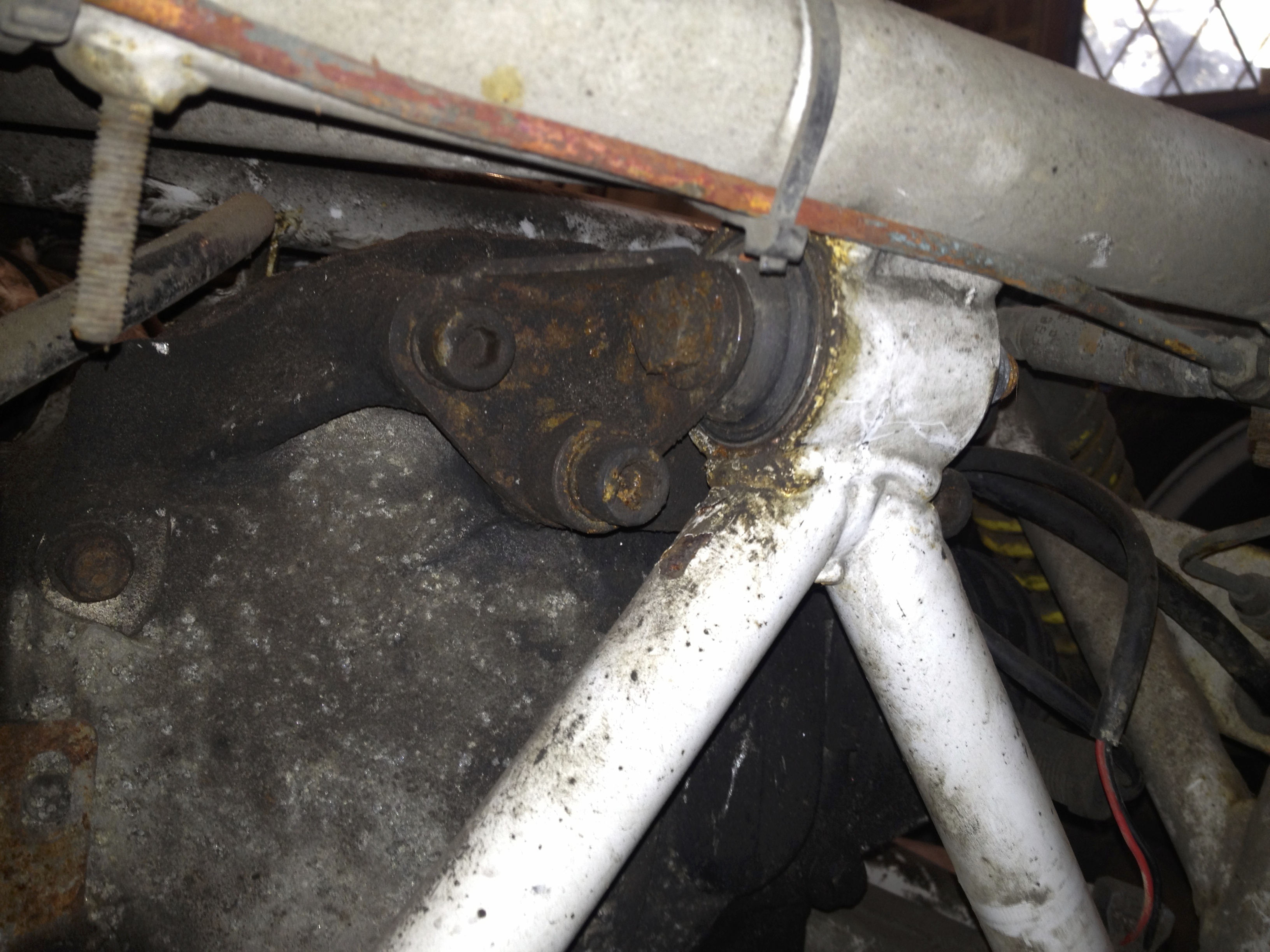 Above 2 pictures of the rear mount bracket
I undid the 4 allen headed bolts on the rear bracket and left it attached to the chassis as I removed the diff. Didn’t seem to get in the way.
Next thing is to unbolt the inner drive shafts. Pretty easy, just undo the 12 bolts (6 on each shaft). Thats it.
So, to the actual removal. I started by placing the trolley jack under the diff and lifting it slightly just to get everything moving. I left the jack where it was and physically lifted/manhandled the diff around 90 degrees until the drive shaft flanges were pointing straight up to the sky and down to the floor. No pictures i’m afraid. No way could you manage this one handed whilst taking photos with the other. Once I had the diff balanced on its side on the jack I lowered the jack slowly, moving the diff around with the other hand as it came out of the bottom of the chassis. Unfortunately this is much harder than it sounds. Just keep at it, it will come out of the bottom of the chassis, it just doesn’t seem like its possible to start with. Of course the next problem you encounter is that the trolley jack is now fully lowered, the diff is still resting on it and you realise the chassis is too low to allow the diff to slide out from underneath. No problem, just jack the chassis up and pull the diff out… except of course the jack is under the diff and can’t be easily removed. Balls ! A second jack is a life saver hear, even just the standard scissor lack that comes with the car. Lift the chassis slightly and the diff can be pulled out from under the chassis. Phew … another hurdle cleared.
All thats left is the easy (sort of) ancillary stuff.
Remove the outer drive shaft bolts from each rear hub and then fully remove the shafts. Remove the diff mounting brackets from the chassis. Just 3 bolts that pass through the large rubber bushes (these bushes can be seen in the above photos so please scroll back up if needed)
Having removed all the cable ties earlier on will help here. Remove the fuel filter bracket and fuel pump. The filter bracket attaches to the chassis on the near side rear upper part of the chassis. The pump location is mentioned earlier. The bracket for the pump sits on 2 threaded lugs on the chassis. Just remove the nuts and pull the pump away.
Same picture as above. The filter is the large silver cylinder at the lower centre of the picture
 Filter bracket fixings
 Another view of the fuel pump
Lets have a go at the brake calipers.
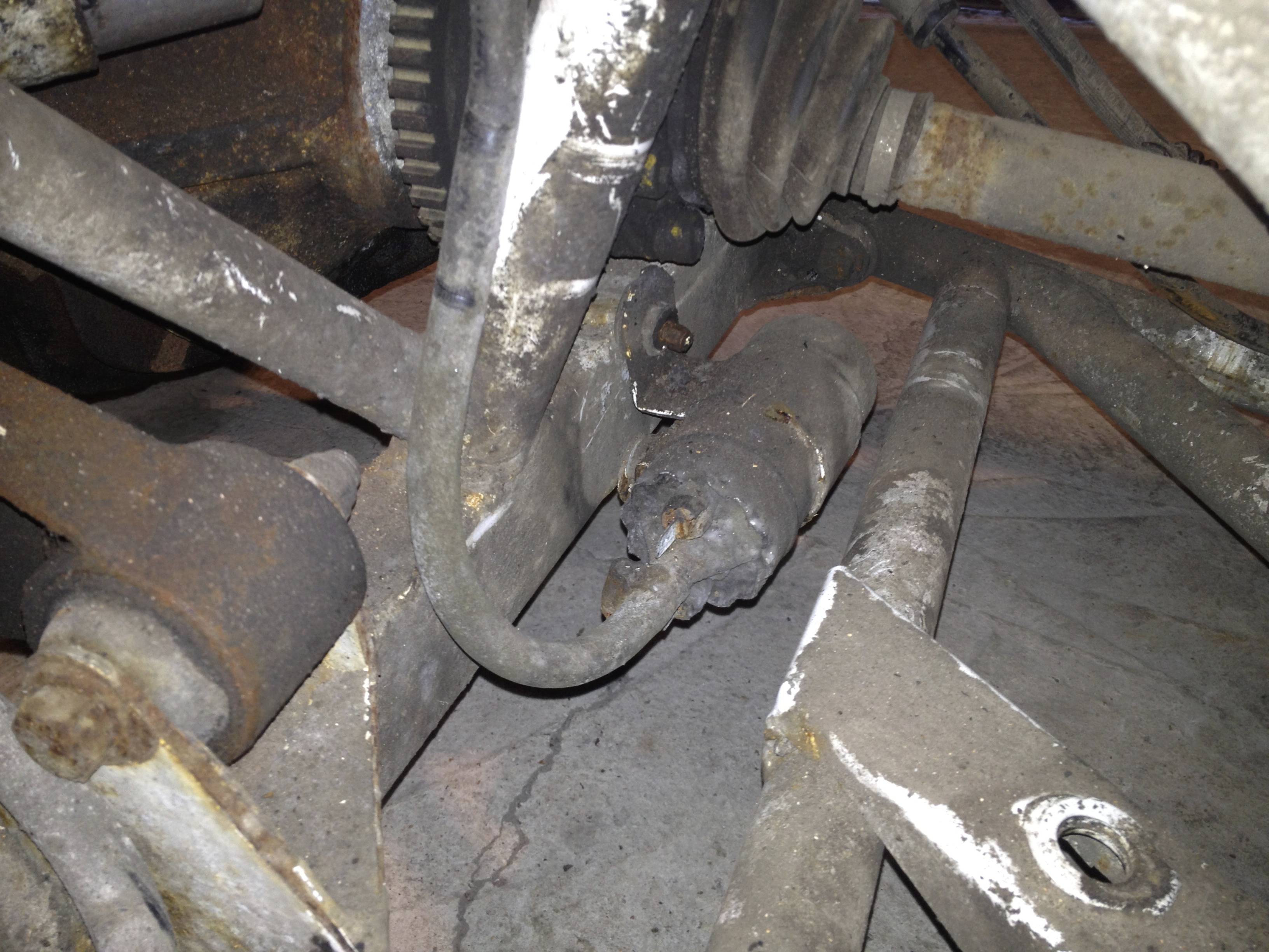
The fronts aren’t too much of a problem. There are 2 allen headed bolts holding the caliper to the hub. Careful as there is also a spacer on each bolt between the hub and caliper, don’t lose these as they are needed. The bolts can take quite a heave to get going as they should be assembled with locktite. Once on the move then there should’t be a problem. When they are out the caliper can be pulled off the disk and away from the hub. The flexible hose then unscrews from the caliper end and passes through a grommet in the hub before being attached to the chassis. The attachment takes the form of the hose being passed through the chassis and then a nut screwing on from the other side, thus locking the hose to the chassis.
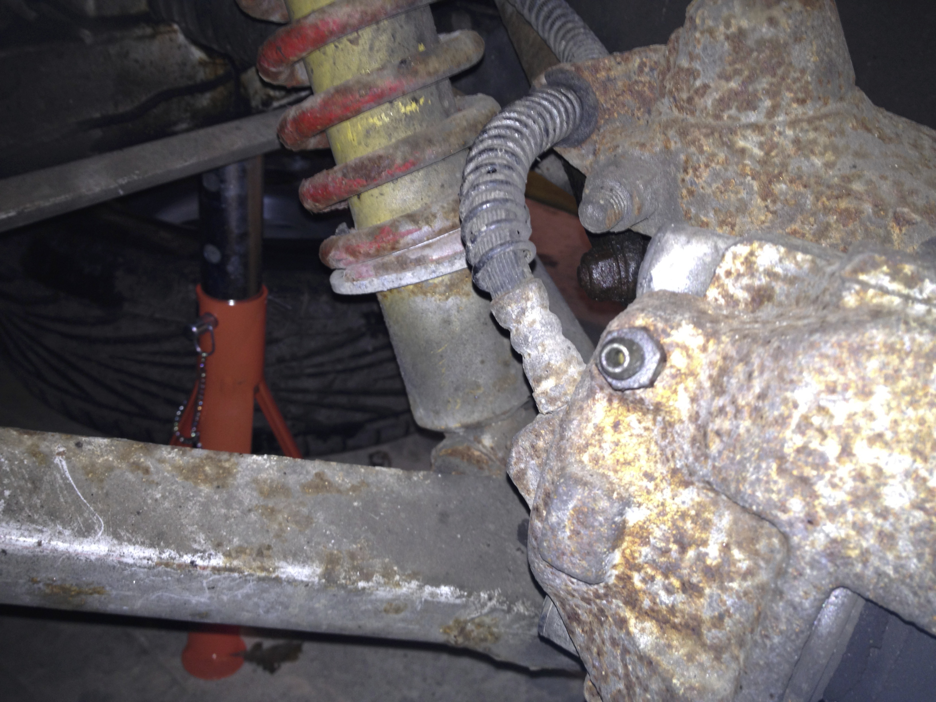 Flexible hose exiting the caliper and passing through the grommet in the hub
 Flexible hose continuing its journey to the chassis mounting point
 The small bracket at the top left of centre of picture is where the front near side flexible hoses connect to the chassis (identical bracket on off side as well).
Now the 3 way brake union at the very rear of the car mentioned in a previous section. A simple nut to undo and the union slides down.
 3 way union
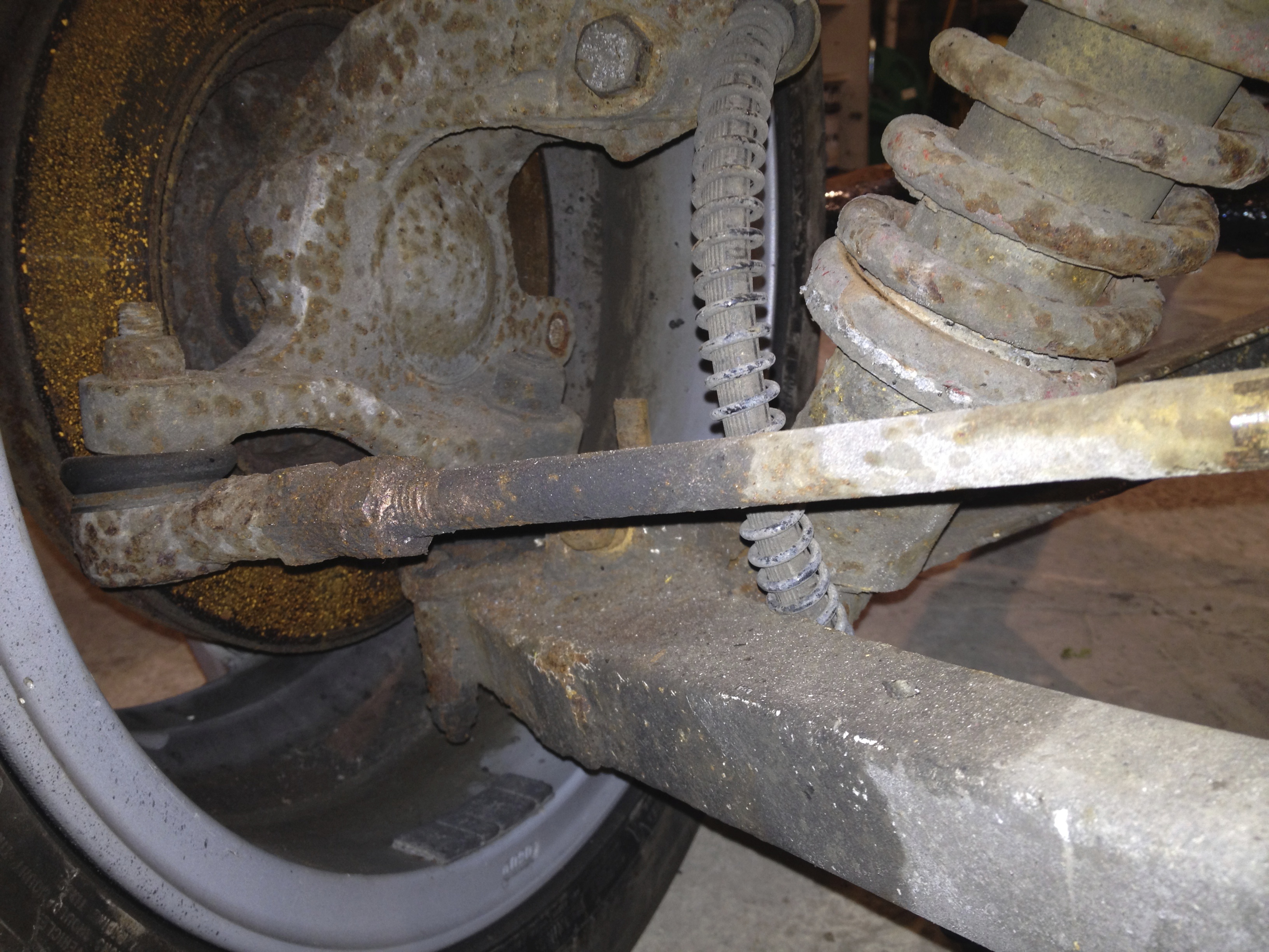
The rear brakes are similar up to a point. The flexible hoses attach to the chassis in the same style as the fronts. The fitting to the caliper though is a banjo bolt, easy to undo. The handbrake cable end must be unhooked from the spring on the caliper and then pushed through the caliper. It can take a good heave to get this out, so knocking it out with a drift is fine. It’s just a push fit, but its normally wedged in there due to being covered in years of dirt and grime.
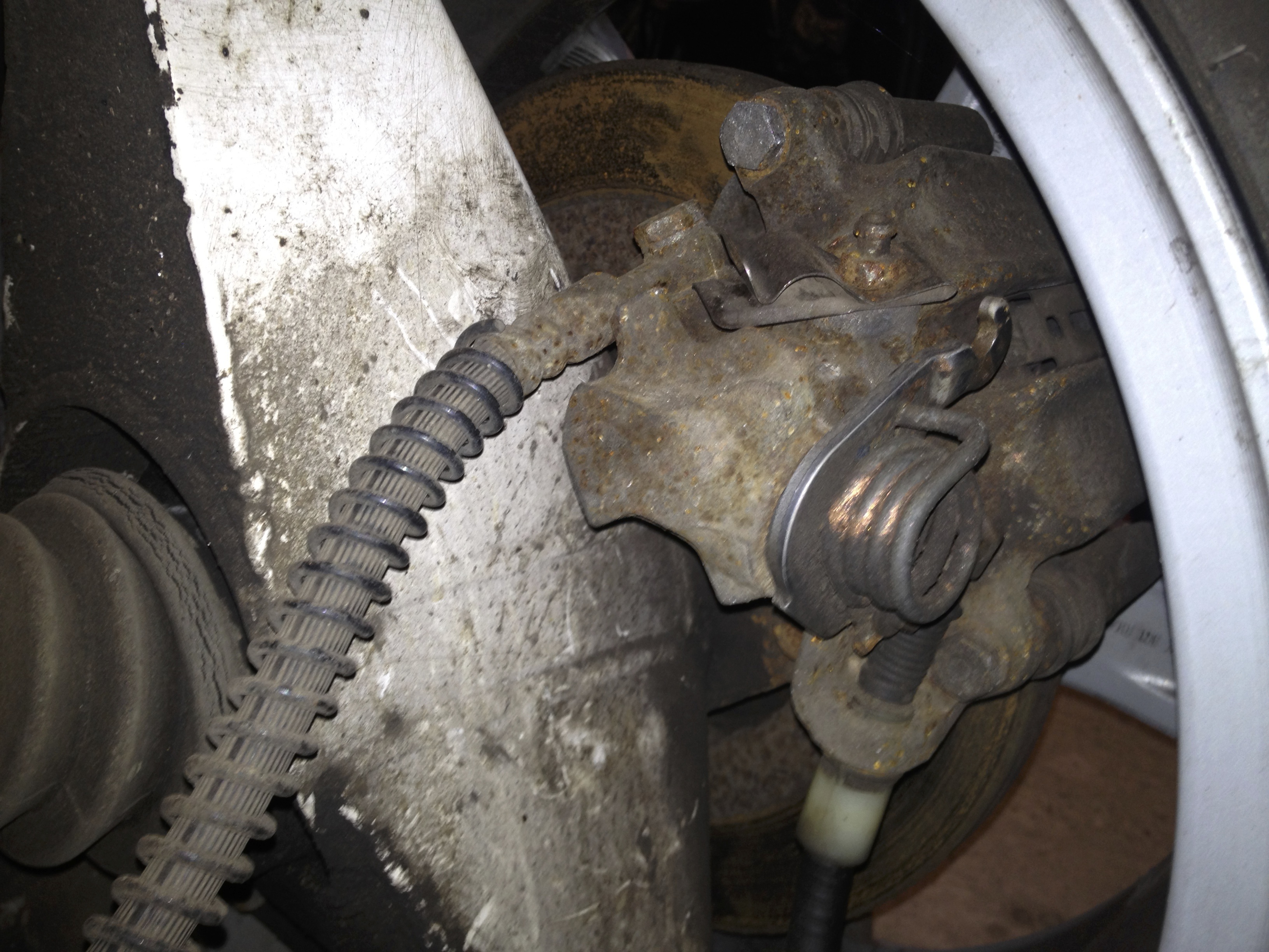 Rear caliper. Note banjo bolt for the flexible pipe at the top. Handbrake cable lower right. The cable has already been released from the spring and pulls through/must be drifted out towards the bottom of the picture.
 Flexible rear hoses attaching to the chassis. Also notice handbrake cable just below and left.
What is not so much fun with the rears is removing the calipers. The top allen bolt can be very difficult to get at. The trouble is that the hub is in the way. When you are looking at the problem you’ll understand immediately what I’m trying to describe. I had to cut down the short end of an allen key with the dremel as this was the only way it would fit in. Added to the fact that locktite should have been used again and this bolt can be a real pain to get out. Keep at it and you should get there. Slipping some pipe (I used an old spark plug extension I had lying around) over the long end of the allen key not only saves your hand from being ripped to shreds, but also allows more leverage to be applied. The lower bolt is easy. Plenty of room for an allen socket. There we are, the calipers are off.
 Cut down allen key
 Cut down key compared to standard size
Now all the brake copper pipes can come out. Just carefully remove them, nothing much else to it.
Remove the copper and rubber fuel piping running down the near side of the chassis.
Same picture as above for the remote linkage, but now we are concentrating on the fuel piping running along the chassis and then up and over the bell housing. The rubber pipe is what you removed from the fuel rail on top of the engine a few sections ago.
There is also another copper and rubber pipe for the fuel return to the tank that runs down the off side. I’d rather not dwell too long on the pipe routing. I’ve seen quite a few photos where the routing is quite different, so really it depends on what your car has and how you fancy doing it when replacing.
Next the handbrake. Very easy, just 2 bolts that attach it to the chassis. Take note of the placement of washers below.
 Handbrake
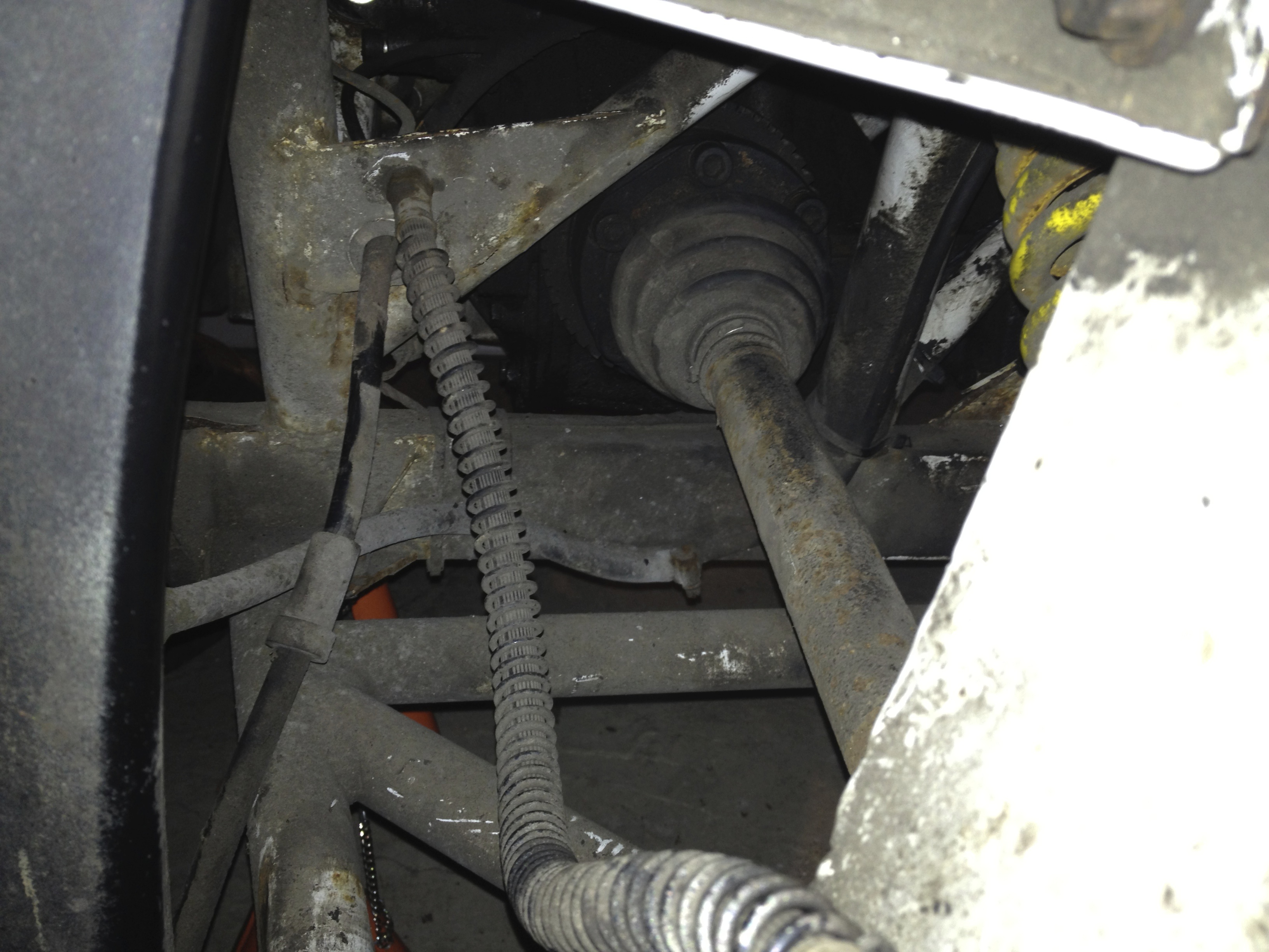
Once that is removed the handbrake cable can be pulled and threaded out of the chassis. All that is needed is to release it from the 2 brackets above the diff (pictured below).
Lastly we have the front ARB.
Pretty easy again. The bar is attached to the chassis via 2 clamps and then via 2 drop links to the front wishbones. Just undo all the bolts and the bar can be pulled out. Careful, it is heavier than it looks !
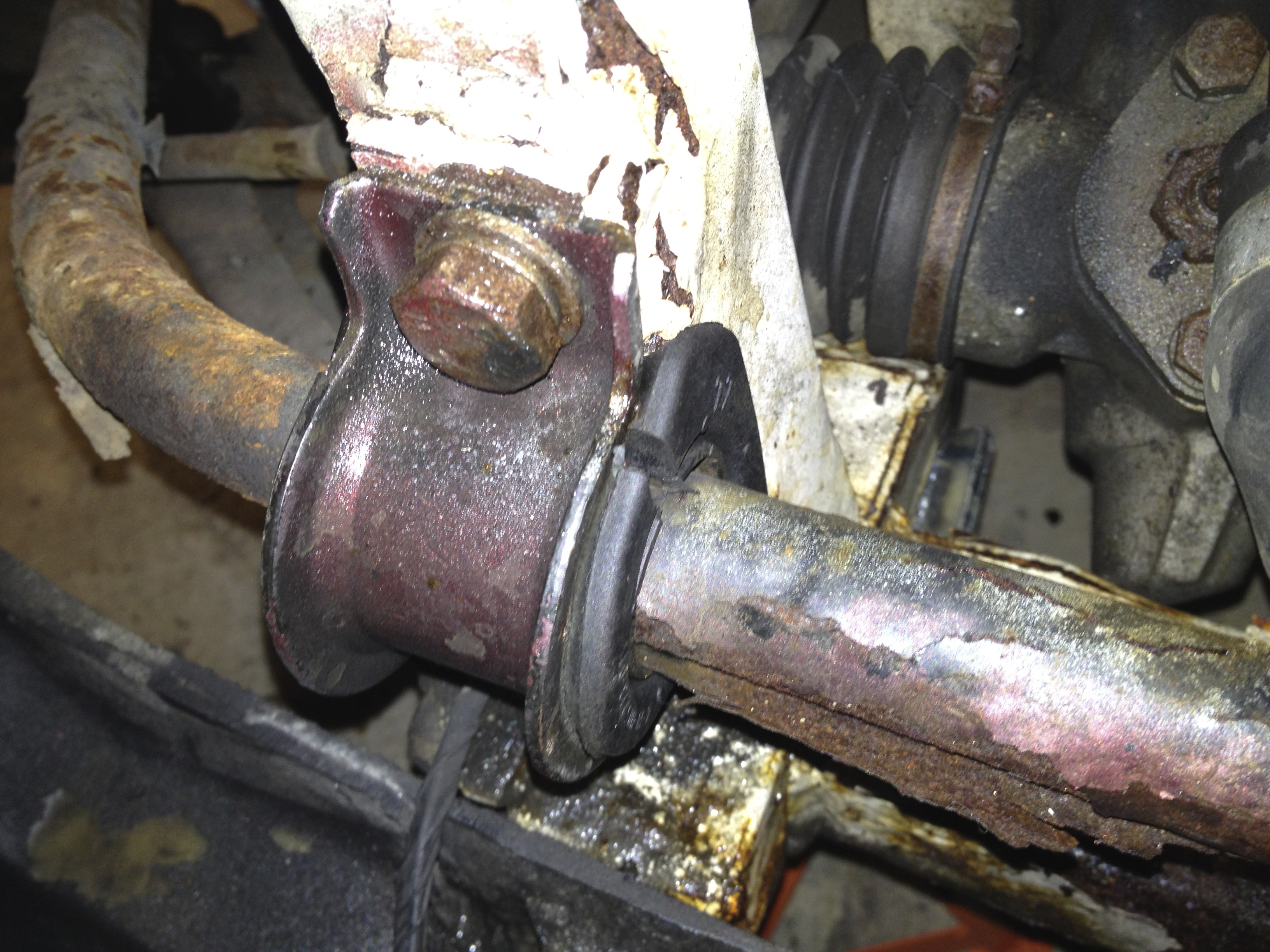 Off side mount
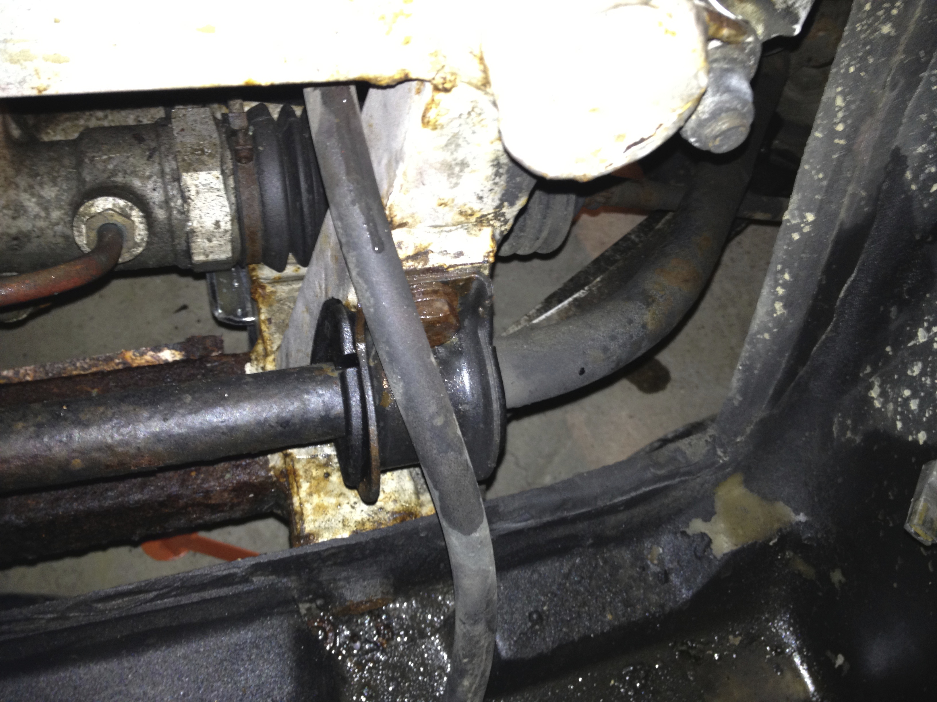 Near side mount
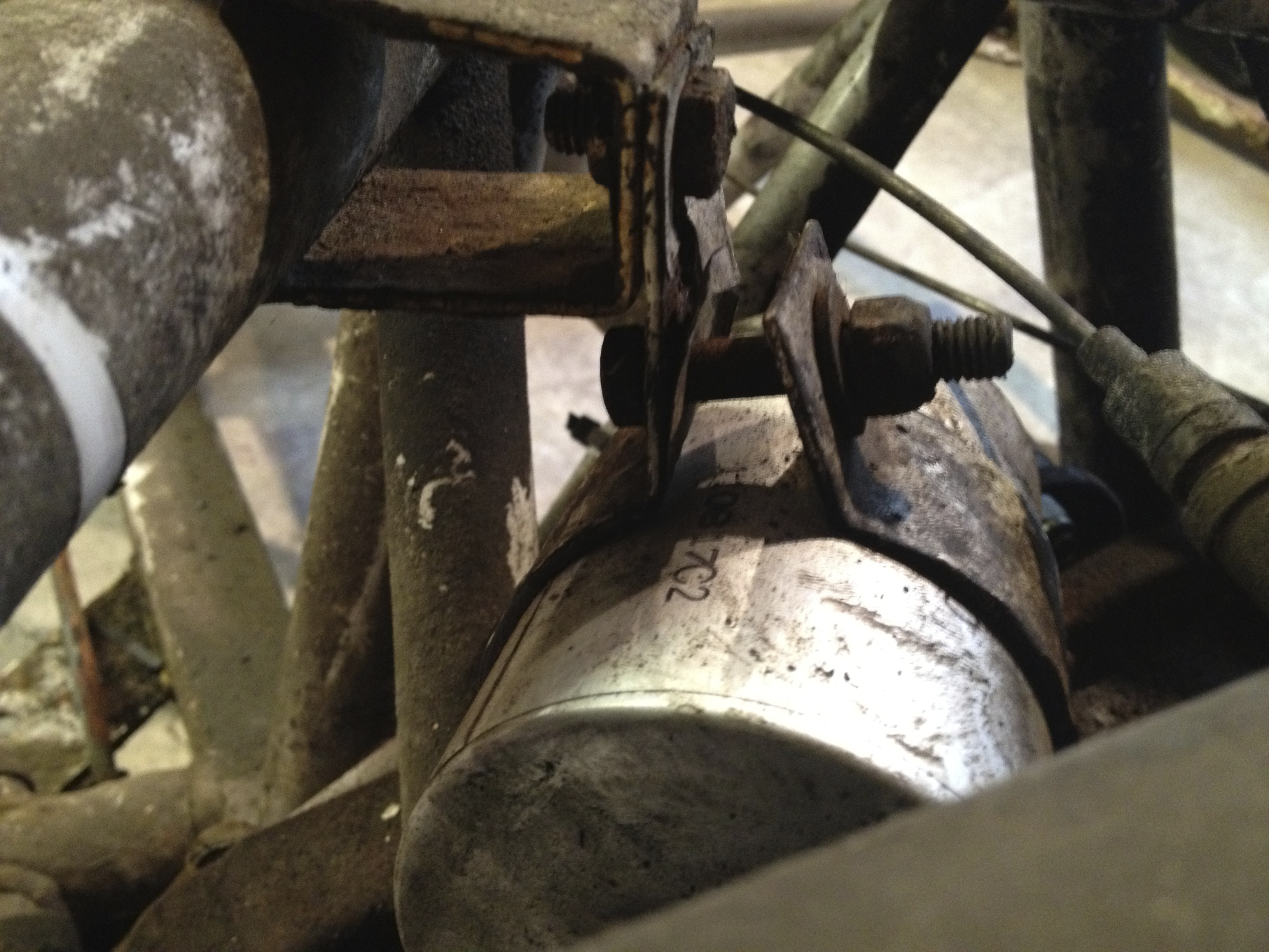
 Droplink in the middle of the picture attaching ARB to wishbone (the dark patches are penetrating fluid)
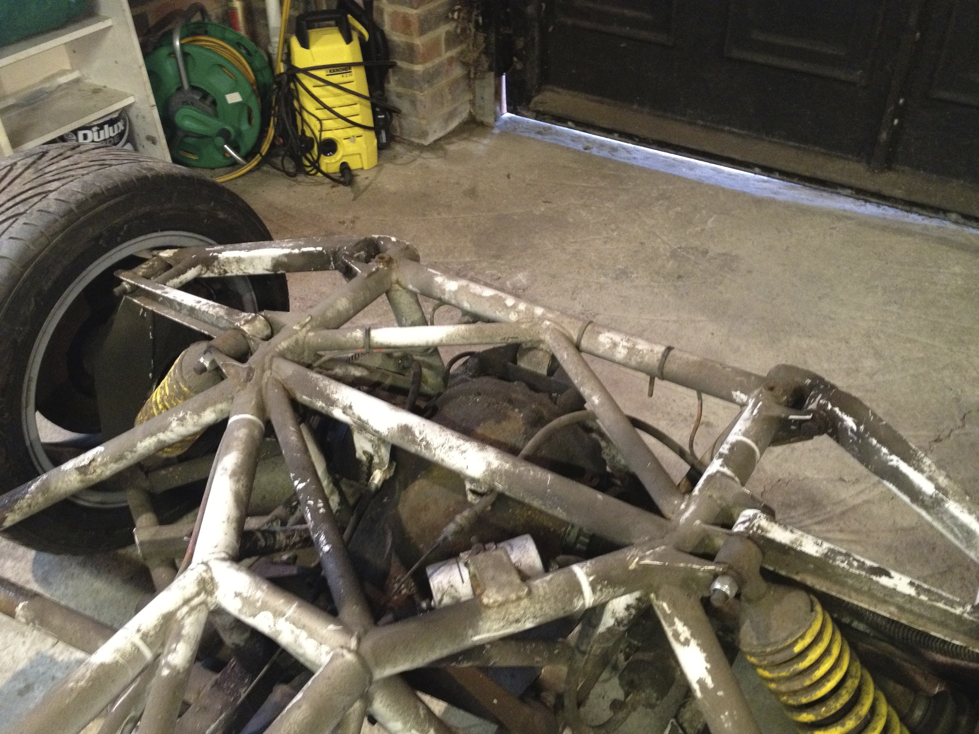
Well, that should pretty much be it. The below picture is what I ended up with which is how I agreed it would be collected. The chassis still has the shocks and steering rack fitted, but virtually nothing else.


Needless to say of course that as you’re removing things from the chassis, if you’re not sure what things are or if you think you might forget then label them. In fact scratch that, label everything anyway ! You will forget things and this will make life so much easier in the long run.
